Device and method capable of reducing hydrodynamic deep drawing pressure pad force

A technology of liquid-filled deep drawing and blank-holding force, which is applied in the field of liquid-filled deep-drawing devices, can solve problems such as high blank-holding force, unfavorable flange deformation and flow, and increased frictional resistance, so as to reduce equipment requirements and avoid cracking defects , the effect of reducing the tensile stress

Active Publication Date: 2011-11-23
天津哈工永兴科技有限公司
View PDF7 Cites 13 Cited by
  • Summary
  • Abstract
  • Description
  • Claims
  • Application Information

AI Technical Summary

Problems solved by technology

Due to the pressure distribution formed by the fluid on the lower surface of the flange area of ​​the blank during the deep drawing process, there is a mechanical balance between the fluid pressure in the flange area and the blank holder force. The force increases the frictional resistance between the upper surface of the flange area and the blank holder ring, which is not conducive to the deformation flow of the flange
In addition, for larger formed parts, the area where the fluid acts on the flange area is larger, and the blank-holding force required to balance the fluid pressure on the lower surface of the flange area is also high, and the blank-holding force of the equipment for liquid-filled deep drawing often cannot Meet the requirements of large tonnage

Method used


Image

  • Device and method capable of reducing hydrodynamic deep drawing pressure pad force
  • Device and method capable of reducing hydrodynamic deep drawing pressure pad force
  • Device and method capable of reducing hydrodynamic deep drawing pressure pad force

Examples


specific Embodiment approach 1

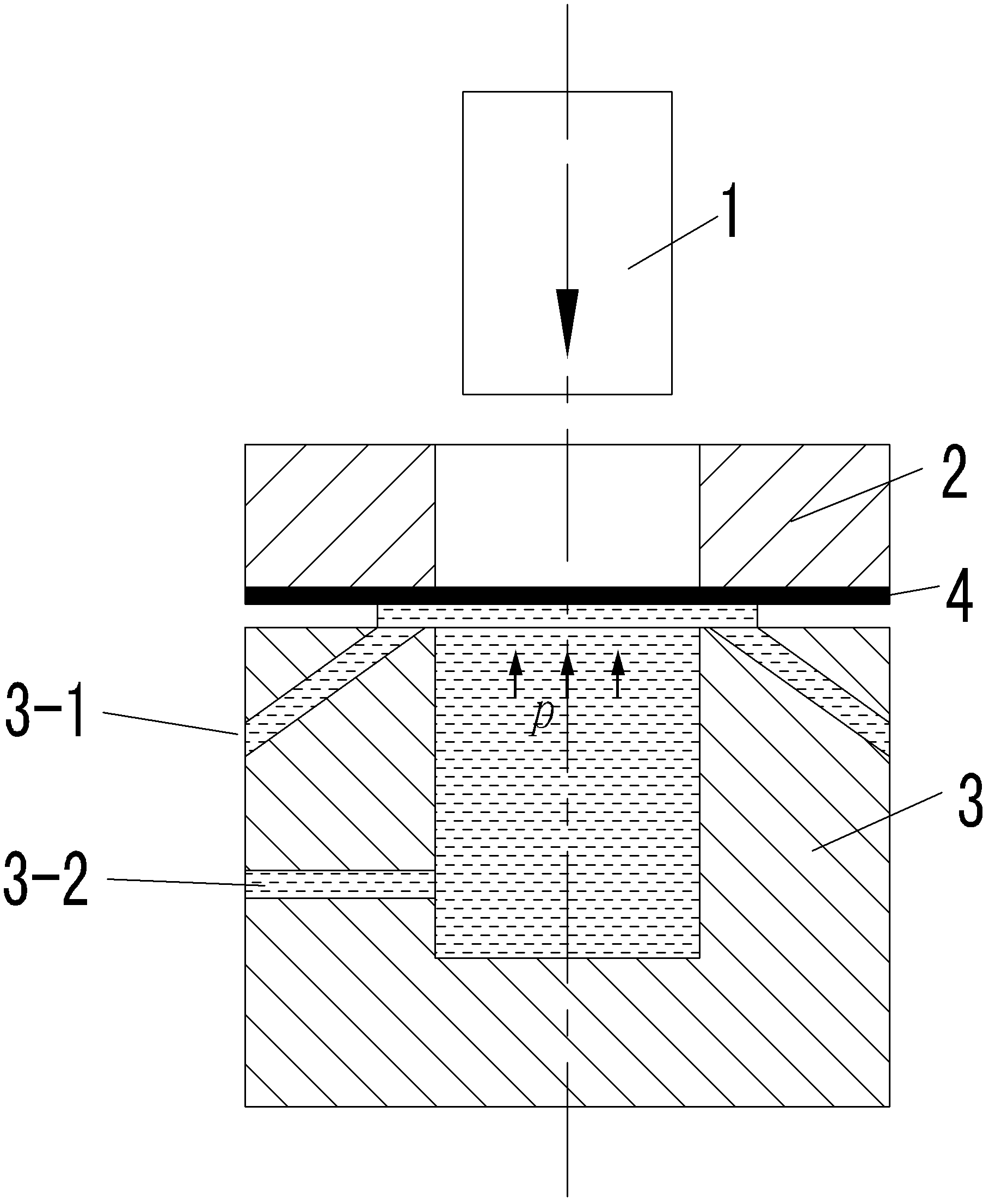
[0017] Specific implementation mode one: as Figure 1~5 As shown, the device for reducing the blank-holding force in liquid-filled deep drawing described in this embodiment includes a punch 1, a blank-holder 2 and a liquid-filled chamber 3. The upper end of the liquid-filled chamber 3 is open, and the punch 1 is placed in the filled Above the liquid chamber 3 and corresponding to the opening of the liquid-filled chamber 3, the blank holder 2 is located above the liquid-filled chamber 3 for fixing the sheet blank 4; its feature is that a liquid drainage channel is provided on the upper end surface of the liquid-filled chamber 3 3-1, the liquid drainage channel 3-1 communicates with the atmosphere from the inlet on the upper end surface of the liquid-filled chamber 3 until it passes through the outlet on the side wall of the liquid-filled chamber 3 (the inlet of the liquid drainage channel 3-1 is in the liquid-filled On the upper end surface of the chamber 3, the outlet of the l...

specific Embodiment approach 2

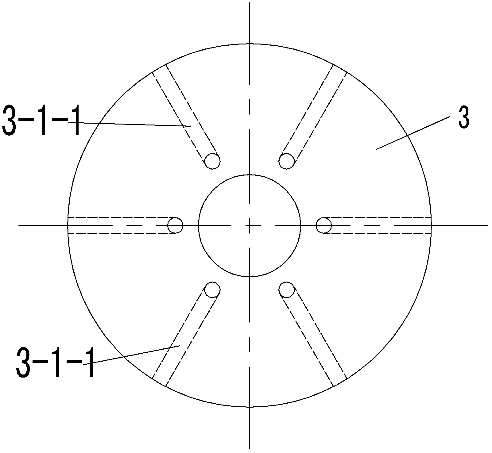
[0019] Specific implementation mode two: as Figure 1~2 As shown, the liquid drainage channel 3-1 in this embodiment is composed of a plurality of liquid drainage holes 3-1-1, and the plurality of liquid drainage holes 3-1-1 are uniformly arranged in the liquid-filled chamber 3 along the circumference. In the side wall, each liquid drainage hole 3-1-1 is arranged obliquely; the inlet of each liquid drainage hole 3-1-1 is on the upper end surface of the liquid-filled chamber 3, and each liquid drainage hole 3-1-1 The outlet of 1-1 is on the outer wall of the liquid-filled chamber 3 . Other components and connections are the same as those in the first embodiment.

specific Embodiment approach 3

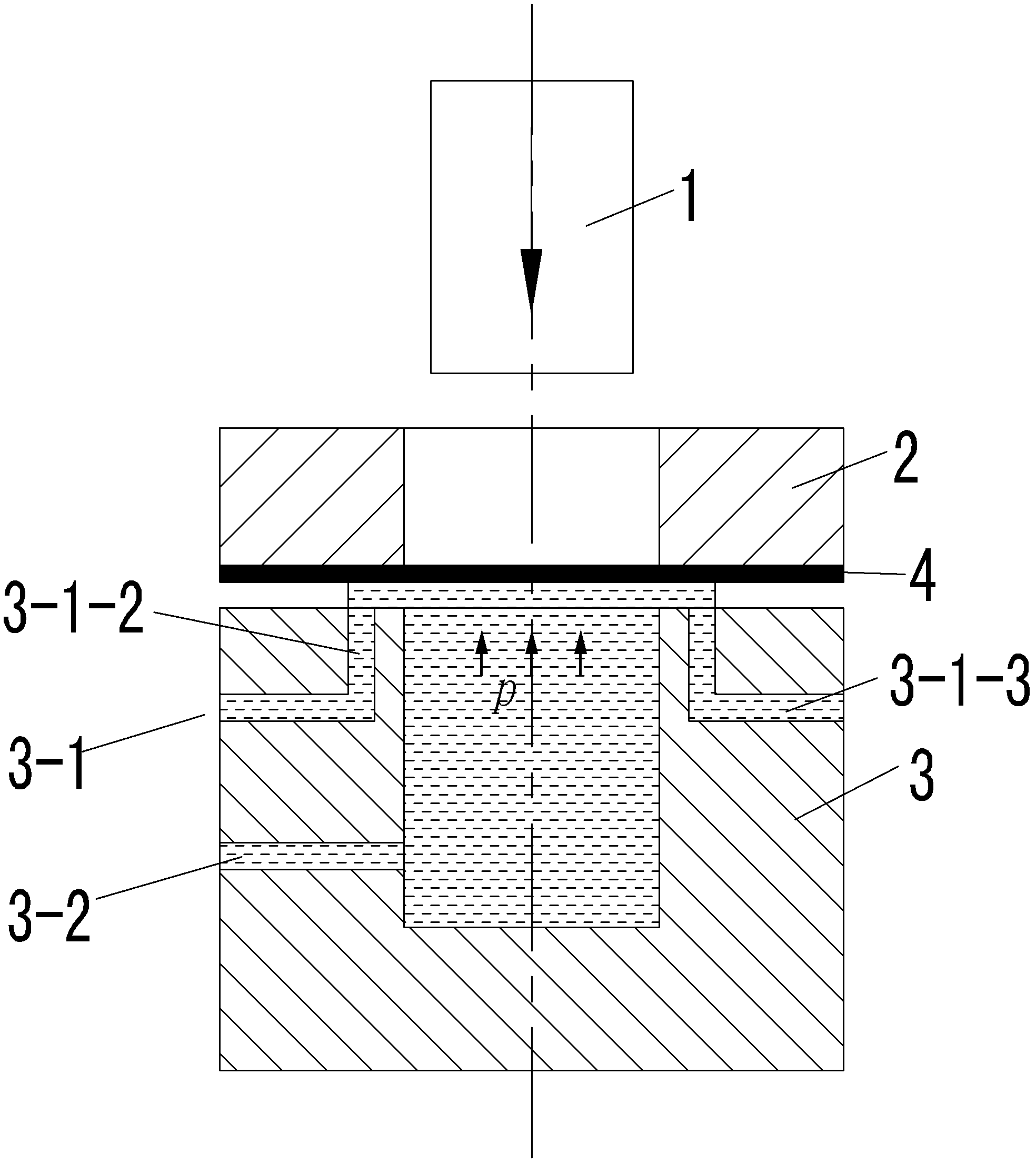
[0020] Specific implementation mode three: as Figure 3-4 As shown, the liquid drainage channel 3-1 in this embodiment is composed of an annular drainage groove 3-1-2 and a plurality of liquid drainage holes 3-1-3 located at the lower part of the drainage groove 3-1-2. The annular drainage groove 3 -1-2 is opened on the upper end surface of the liquid-filled chamber 3, a plurality of liquid drainage holes 3-1-3 are uniformly arranged in the side wall of the liquid-filled chamber 3 along the circumference, and each liquid drainage hole 3-1- 3 are arranged horizontally, and the inner end of each liquid drainage hole 3-1-3 communicates with the inner cavity of the annular drainage groove 3-1-2. Other components and connections are the same as those in the first embodiment.


PUM


Abstract

The invention provides a device and method capable of reducing hydrodynamic deep drawing pressure pad force, relating to a hydrodynamic deep drawing device and method used for reducing pressure pad force. The invention provides a processing device and a processing method capable of reducing the pressure pad force, aiming at reducing the pressure pad force required in a hydrodynamic deep drawing process and improving forming limit. The device comprises a male die (1), a pressure pad (2) and a charging chamber (3), the upper end of the charging chamber (3) is open, and the end face of the charging chamber (3) is provided with a liquid drainage channel (3-1) which is communicated with the side wall of the charging chamber (3). The processing method sequentially comprises the following steps of: injecting fluid medium into the charging chamber (3), placing plate blank, applying the pressure pad force, and controlling the male die (1) to move down so as to pressurize. By adopting the device and method provided by the invention, the pressure pad force can be reduced, friction between blank and the pressure pad can be reduced, and the forming limit of a plate part can be further improved; and tonnage of equipment can be reduced, and processing capacity of the equipment can be obviously improved.

Description

technical field [0001] The invention relates to a liquid-filled deep drawing device and method for reducing blank-holding force. Background technique [0002] Sheet metal liquid-filled deep drawing is a new technology that uses fluid instead of traditional die to transfer load for forming. It is suitable for forming low-plastic materials such as aluminum, magnesium, and high-strength steel, and sheet parts with complex shapes. At present, it is widely used in many fields such as automobiles, aerospace, and kitchen utensils. The working process of sheet metal liquid-filled deep drawing is as follows: firstly, the sheet blank is pressed tightly by applying blank-holding force through the blank holder ring, and then the fluid medium is filled into the liquid-filled chamber. When the fluid pressure meets the requirements, the punch drives the sheet blank to move together. And under the joint action of fluid, it is formed into parts of predetermined shape. Due to the fluid pres...

Claims


Application Information

Patent Timeline
Patent Type & Authority Applications(China)
IPC IPC(8): B21D26/031B21D26/021B21D22/22
Inventor 徐永超苑世剑
Owner 天津哈工永兴科技有限公司
Why Eureka
Try Eureka