Supercharge Your Innovation With Domain-Expert AI Agents!

Method for manufacturing spinning cops

A bobbin and winding technology, which is applied to spinning machines, textiles and papermaking, and continuous winding spinning machines, etc. It can solve the problem of winding speed drop, adverse effects of winder efficiency, low average winding speed, etc. question

Active Publication Date: 2011-11-23
SAURER GERMANY GMBH & CO KG
View PDF5 Cites 5 Cited by
  • Summary
  • Abstract
  • Description
  • Claims
  • Application Information

AI Technical Summary

Problems solved by technology

[0011] With this known method, it is indeed possible to achieve a limitation of the continuously increasing yarn tension in the coping stroke without corresponding measures, thereby significantly reducing yarn breaks; however, in the last third of the coping stroke The reduction in winding speed in the phases results in a relatively low average winding speed, which has a negative effect on the efficiency of this winder

Method used


Image

  • Method for manufacturing spinning cops
  • Method for manufacturing spinning cops
  • Method for manufacturing spinning cops

Examples


Embodiment Construction

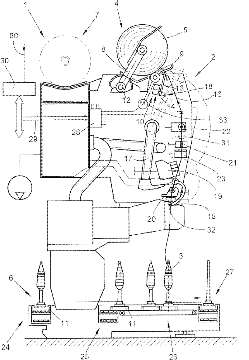
[0028] figure 1 The work station 2 of the winding machine 1 is shown schematically in side view. As already known, in the station 2 of such a winding machine 1 the bobbin 3 produced on the ring spinning machine is rewound into a cross-wound bobbin 5 of a large package.

[0029] After its preparation, the cross-wound bobbin 5 is transferred to the cross-wound bobbin conveying device 7 along the machine length by means of an automatically operating handling device (not shown), preferably a cross-wound bobbin changer, and sent to the Package loading station on the end side of the machine, etc. Furthermore, such a winding machine 1 generally has a logistics device in the form of a bobbin and tube delivery system 6 , in which bobbins 3 or empty tubes are moved in circulation on a delivery disk 11 . figure 1 Only the bobbin supply section 24 of the bobbin transport system 6 , the reversibly driven yarn storage section 25 , one of the transverse transport sections 26 to the work st...


PUM


Abstract

The invention relates to a method for manufacturing spinning cops and a ring spinner by using the method. The spinning cops are the windings on a quill and have the positions and sizes that are specified by the spinning processes of the ring spinner. The optimum position and size of the winding of the spinning cops produced at the work station of the ring spinner is determined according to such a specification, namely, the backing-off characteristics of the spinning cops are measured when at least one spinning cop backs off the work station of the winders.

Description

technical field [0001] The invention relates to a method for producing bobbins according to the preamble of claim 1 and to a ring spinning machine for carrying out the method. Background technique [0002] Ring spinning machines for producing bobbins have been known for a long time and are described in detail in a large number of patent documents. Such textile machines each have a plurality of identical workstations on their machine length sides, which themselves each have various operating elements mounted stationary or vertically displaceable. On each machine length side there is, for example, a creel for accommodating the feed bobbins, a drafting device for drawing the feed sliver provided by the feed bobbins, and a fixed stand for accommodating the rotatably supported spinning spindles. Moving spindle rail. Furthermore, a ring bar for receiving the spinning ring and the traveler, a support for the balloon control ring and a mount for the thread guide are provided verti...

Claims


Application Information

Patent Timeline
Patent Type & Authority Applications(China)
IPC IPC(8): B65H55/04
CPCD01H1/02B65H49/02D01H1/36B65H55/04B65H63/006B65H2701/31
Inventor 马丁·克罗伊施汉斯-于尔根·屈斯特托马斯·魏德
Owner SAURER GERMANY GMBH & CO KG
Features
  • R&D
  • Intellectual Property
  • Life Sciences
  • Materials
  • Tech Scout
  • Unparalleled Data Quality
  • Higher Quality Content
  • 60% Fewer Hallucinations
Learn More