Waste water recycling device for paper making vacuum system and water saving method

A waste water recovery and vacuum system technology, which is applied in the direction of processing waste water treatment, degassed water/sewage treatment, etc., can solve the problems of increased energy consumption in the recovery system, easy generation of sediment and dirt, and rise in temperature of the working fluid, so as to reduce energy consumption. consumption, stable load, and stable vacuum

Inactive Publication Date: 2011-11-23
YONGZHOU XIANGJIANG PAPER CO LTD
View PDF2 Cites 5 Cited by
  • Summary
  • Abstract
  • Description
  • Claims
  • Application Information

AI Technical Summary

Problems solved by technology

However, the structure of the device is complicated, and there are not many applications in the wet end vacuum system of the existing paper machine
[0004] It is generally believed that white water contains a variety of organic substances, inorganic substances and microorganisms, which is prone to sedimentation and dirt, and is not suitable for use as a working fluid for vacuum pumps. At present, clean water is often used as a working fluid for vacuum pumps during work, which consumes more water resources. Some enterprises The working fluid has been recovered and recycled, but the temperature of the working fluid has risen, and the recovery system needs to increase additional energy consumption.

Method used


Image

  • Waste water recycling device for paper making vacuum system and water saving method
  • Waste water recycling device for paper making vacuum system and water saving method
  • Waste water recycling device for paper making vacuum system and water saving method

Examples


Embodiment Construction

[0013] The present invention will be described in further detail below in conjunction with the accompanying drawings and embodiments.

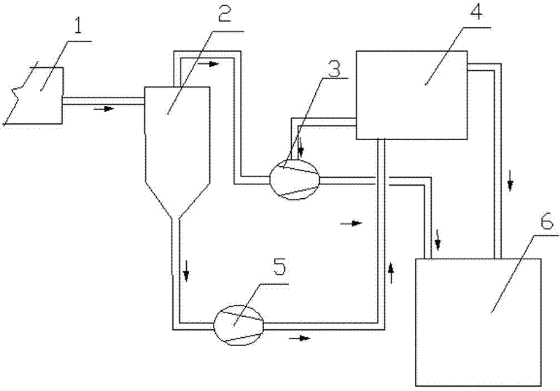
[0014] figure 1 It is a structural schematic diagram of the paper machine wastewater recycling device of the present invention. The paper machine wastewater recycling device includes a vacuum dehydration element 1, an air-water separator 2, a vacuum pump 3, a high-level tank 4, a negative pump 5, a white water pool 6, pipelines, etc., and the air-water separator 2 includes a cylinder, an There is a gas-liquid inlet on one side of the upper part of the body, an air outlet on the top of the cylinder, and a pumping port on the bottom of the cylinder. The gas-liquid inlet is connected to the vacuum dehydration element 1 through a pipeline, and the air outlet is connected to The inlet of the vacuum pump 3 is connected, the discharge outlet 3 of the vacuum pump is connected with the white water pool 6 through a pipeline, the exhaust port of the vac...


PUM


Abstract

The invention discloses a waste water recycling device for a paper making vacuum system and a water saving method. The device consists of a gas-water separator, a vacuum pump, a filtrate pump, a header box, a white water pool and pipelines, wherein the air outlet of the gas-water separator is connected with the inlet of the vacuum pump; the liquid draining outlet of the vacuum pump is connected with the white water pool; the pumping port of the gas-water separator is connected with the inlet of the filtrate pump; the outlet of the filtrate pump is connected with the header box; the lower part of the header box is provided with a liquid outlet; the liquid outlet is connected with the working liquid inlet of the vacuum pump; the upper part of the header box is provided with an overflow port; and the overflow port is connected with the white water pool. In the working process, the mixture of gas and white water of a vacuum dehydrating element is collected into the gas-water separator, the separated gas enters the vacuum pump from the air outlet of the gas-water separator and is emitted into the atmosphere through the vacuum pump, the white water enters the filtrate pump form the pumping port of the gas-water separator and is conveyed into the header box through the filtrate pump, and a part of white water of the header box enters the vacuum pump and is taken as a working liquid instead of clear water.

Description

technical field [0001] The invention relates to a device for recycling papermaking wastewater, in particular to a device for recycling wastewater in a vacuum system of a paper machine. The invention also relates to a water saving method using the device. Background technique [0002] During the papermaking process, the vacuum suction box, vacuum couch roll, vacuum press and felt vacuum roll all need to maintain a certain degree of vacuum. The vacuum system in the wet end of the paper machine is mainly composed of: vacuum dehydration components, air-water separator, vacuum pump, vacuum pipeline And other components, the vacuum pump needs to use working fluid in the working process, and currently clean water is generally used. [0003] The Chinese patent application number is CN200920313700.0, the announcement number is CN201650879U, and the patent titled "gas-liquid separation device" disclosed a gas-liquid separation device on November 24, 2010. The device is used in the...

Claims


Application Information

Patent Timeline
Patent Type & Authority Applications(China)
IPC IPC(8): C02F1/20C02F103/28
Inventor 苏德良王福纪杨爱平刘便初何芳彪
Owner YONGZHOU XIANGJIANG PAPER CO LTD
Why Eureka
Try Eureka