Laser electronic target based on non-diffraction light

A non-diffraction, laser technology, used in instruments, mapping and navigation, measuring devices, etc., can solve the problems of the reduction of target system accuracy and working stability, the limitation of the system's spatial angle measurement accuracy, and the influence of laser spot center coordinates, etc. Achieve the effect of reducing development intensity, strong anti-environmental light interference ability, and easy engineering implementation

Inactive Publication Date: 2011-11-23
HUAZHONG UNIV OF SCI & TECH
View PDF5 Cites 10 Cited by
  • Summary
  • Abstract
  • Description
  • Claims
  • Application Information

AI Technical Summary

Problems solved by technology

This system has the following disadvantages: First, the limitation of the angle measurement accuracy of the inclinometer leads to the limitation of the measurement accuracy of the space angle in the whole system; second, the drift of the inclinometer due to the influence of environmental temperature and other factors is relatively serious; Different measurement approaches or methods are used for each angle on the surface. In theory, it is difficult to measure all spatial angles at the same time. When the attitude of the equipment changes rapidly, the measurement accuracy will be seriously affected; the fourth is due to the phase difference, spherical aberration, and ambient light interference in the optical path system. Factors such as affecting the coordinates of the center of the laser spot
These will lead to the reduction of the accuracy and working stability of the target system, affecting the accurate measurement of space angles

Method used


Image

  • Laser electronic target based on non-diffraction light
  • Laser electronic target based on non-diffraction light
  • Laser electronic target based on non-diffraction light

Examples


Embodiment Construction

[0018] The preferred embodiments of the present invention will be further described in detail below in conjunction with the accompanying drawings.

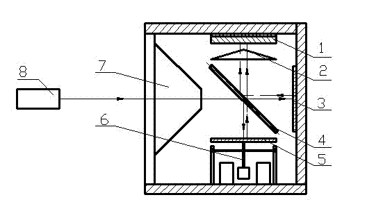
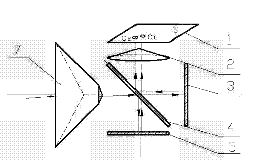
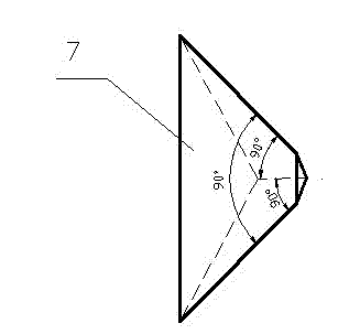
[0019] Such as figure 1 As shown, the specific devices needed to realize this example: a beam splitter 4 with a transmittance of 50%, two plane mirrors 3 and 5, a damped gravity pendulum 6, a conical lens 2 and a cube-corner pyramid lens 7, cubic The upper and lower bottom surfaces of the pyramidal prism lens are parallel, and a CCD image sensor is used to capture the non-diffraction light spot.

[0020] The photosensitive surface of the CCD image sensor 1 and the bottom plane of the conical lens 2 are parallel to each other and the center is coaxial, and form an angle of 45 degrees with the beam splitter 4. The plane mirror surface 5 is fixed on the damped gravity pendulum 6, under the action of the damped gravity pendulum, its plane normal does not change with the rolling of the target, and always remains in the direction of gravity....


PUM


Abstract

The invention discloses a laser electronic target based on non-diffraction light. Laser transmitted by a cube corner pyramid lens enters a light splitting circuit and is divided into a horizontal beam and a vertical beam; the horizontal beam is reflected by a plane mirror and a beam splitter and then enters a conical lens to form a non-diffraction light spot O2; an image information processing system captures the non-diffraction light spot O2, and a horizontal yaw angle and an inclination angle of an object to be measured can be obtained by calculation of the center coordinate of the non-diffraction light spot; the vertical beam is reflected by the plane mirror on a gravity pendulum with damp, is projected into the beam splitter and enters the conical lens to form a non-diffraction light pot O1; and the image information processing system captures the non-diffraction light and acquires the roll angle of the object to be measured according to the calculation of the center coordinate of the non-diffraction light pot O1. The laser electronic target realizes all-optical space angle measurement based on the non-diffraction light, and has the characteristics of high space angle measurement accuracy, stability, and ambient light interference resistance capacity and compact structure.

Description

Technical field [0001] The invention belongs to the technical field of space angle measurement, and specifically relates to a laser electronic target based on non-diffracted light, which is used for positioning and guiding large equipment systems such as shield machines. Background technique [0002] At present, gyro-oriented and laser-oriented technologies are mainly used for attitude measurement and guidance during operation of large-scale equipment systems. The gyroscope uses the mechanism that the angular momentum and direction of the high-speed rotating rotor remain unchanged in the inertial space to achieve the measurement of the spatial angle, but it has the disadvantages of large time lag and azimuth drift. The German ZED and VMT laser guidance systems based on laser orientation technology, with different measurement principles, can well measure the space angle and realize the attitude measurement and guidance of the equipment, but the optical path system is more complica...

Claims


Application Information

Patent Timeline
Patent Type & Authority Applications(China)
IPC IPC(8): G01C1/00
Inventor 赵斌马国鹭
Owner HUAZHONG UNIV OF SCI & TECH
Why Eureka
Try Eureka