Correction method for on-track aberration of star sensor

A technology of star sensor and optical aberration, applied in the field of space science, can solve the problems of processing and assembly error, electronic circuit noise, optical system imaging error, etc.

Inactive Publication Date: 2011-11-23
HARBIN INST OF TECH
View PDF6 Cites 46 Cited by
  • Summary
  • Abstract
  • Description
  • Claims
  • Application Information

AI Technical Summary

Problems solved by technology

[0003] The star sensor is a high-precision instrument, but there are many error sources, such as installation, thermal deformation and other errors, as well as optical system ...

Method used


Image

  • Correction method for on-track aberration of star sensor
  • Correction method for on-track aberration of star sensor
  • Correction method for on-track aberration of star sensor

Examples


Embodiment 1

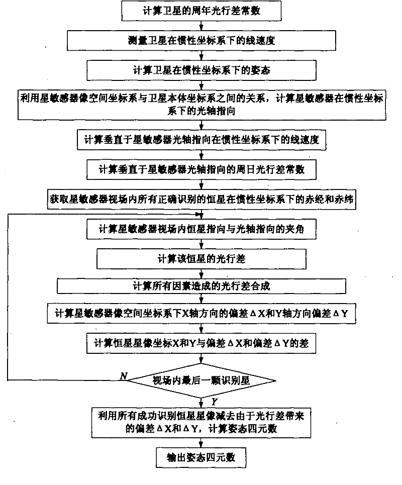
[0033] Example 1: Combining image 3 , a correction method for on-orbit aberration of a star sensor, the steps are as follows:

[0034] Step 1: According to the formula Calculate the annual aberration constant of the satellite; in the formula: α is the inclination angle of the aberration error, μ is the angle between the apparent direction of starlight and the direction of the earth's motion, V is the linear velocity of the earth's revolution, and c is the speed of light;

[0035] Step 2: Use the spaceborne equipment to measure the linear velocity of the satellite in the inertial coordinate system;

[0036] Step 3: Use the spaceborne inertial device to measure the three-axis attitude of the satellite in the orbital coordinate system, and then calculate the attitude of the satellite in the inertial coordinate system;

[0037] Step 4: According to the attitude of the satellite in the inertial coordinate system, and the relationship between the star sensor image space coordina...

Embodiment 2

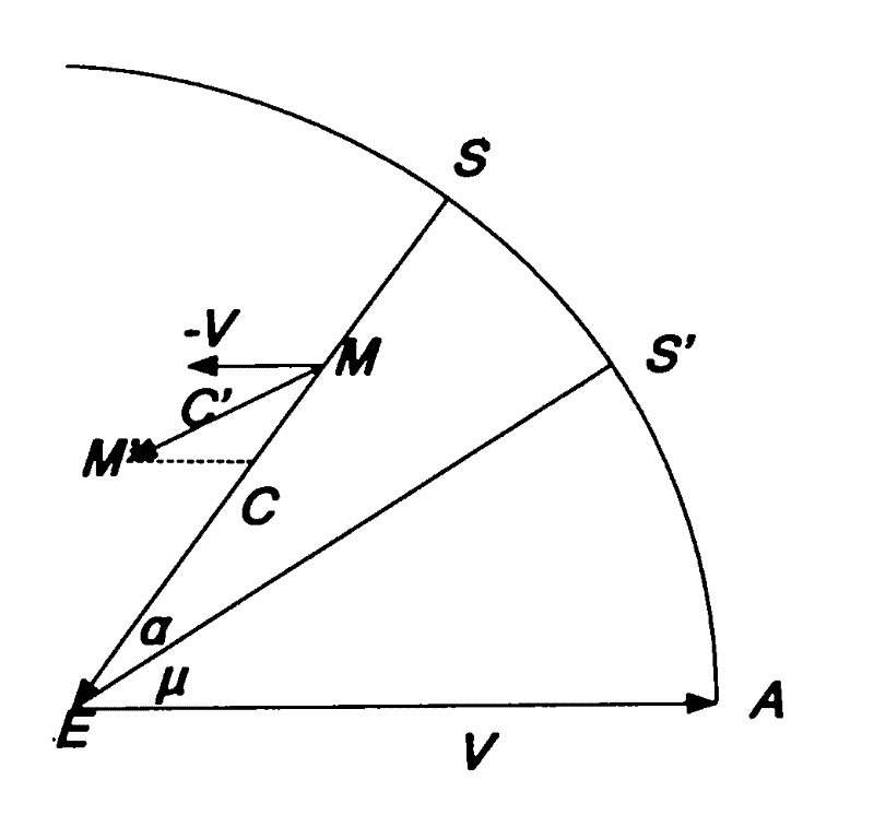
[0048] Example 2: Combining figure 1 , figure 2 , Figure 4-Figure 8 , Aberration is defined as: due to the movement of the star sensor with the vehicle and the finite speed of light, the apparent displacement of the position of the star in the direction of the movement of the star sensor. When the incident light of the star is perpendicular to the motion direction of the star sensor, the aberration error is the largest. Schematic diagram of aberration as

[0049] figure 1 shown. The motion of the earth relative to the sun causes the aberration calculation process as follows: the light emitted by the star will also appear to be inclined toward the earth (the apparent direction) when viewed on the moving earth reference system, and the aberration error inclination angle is defined as α. α is determined by the speed of light c and the linear velocity V of the earth's revolution, the formula is as follows:

[0050] tgα = V ...

Embodiment 3

[0080] Embodiment 3: as Figure 9It is an implementation method for on-orbit aberration correction of star sensors. In addition to outputting to satellites, the orbit information output by on-board GPS is also output to star sensors in real time. All star image coordinates, at this time due to aberration, all star image coordinates have deviations, so these star image coordinates cannot be directly used to calculate attitude information, and because the angle between the star pointing and the optical axis pointing is different, the resulting The deviations are also different, so first the deviation of these stellar image coordinates due to aberration must be calculated. The method of calculating the deviation of star image coordinates is as follows: calculate the current satellite’s rough attitude according to the output of the satellite gyroscope, calculate the optical axis pointing of the star sensor according to the installation angle between the star sensor and the satelli...


PUM


Abstract

The invention provides a correction method for on-track aberration of a star sensor. The method comprises the following steps of: calculating the annual aberration constant of a satellite according to a formula; measuring the linear velocity of the satellite in an inertial coordinate system by using a satellite borne device; calculating the altitude of the satellite in the inertial coordinate system; calculating the optical axis direction of the star sensor in the inertial coordinate system; calculating the linear velocity vertical to the optical axis direction of the star sensor in the inertial coordinate system; calculating the diurnal aberration constant vertical to the optical axis direction of the star sensor; calculating the included angle between a fixed star direction and the optical axis direction in the view filed of the star sensor; calculating aberration synthesis caused by all factors; and calculating an altitude quaternion. In the invention, a mathematical model for eliminating the diurnal aberration and annual aberration of the star sensor and the peculiar motion aberration of the sun is induced; after the model is used to eliminate aberration, altitude information with high accuracy can be further provided for an aircraft, the angular speed of a non-gyro aircraft can be calculated by using altitude, and the accuracy of angular speed calculation can be further improved.

Description

(1) Technical field [0001] The invention relates to space science, in particular to a correction method for on-orbit aberration of a star sensor. (2) Background technology [0002] The position of any star on the celestial sphere is determined. Therefore, the star sensor that realizes the capture and tracking of stars becomes the measuring device used to accurately determine the flight attitude of the spacecraft. It takes the star system that can be precisely positioned as the absolute reference system, and obtains the attitude of the spacecraft through the observation, identification and calculation of the stars. Since the position of the star is defined in the inertial coordinate system, each attitude estimation of the star sensor is a real-time direct measurement of the sensor relative to the inertial coordinate system, and these measurements will not have systematic bias like the gyro-based attitude determination system and slow drift. The star sensor attitude measurem...

Claims


Application Information

Patent Timeline
IPC IPC(8): G01C21/02
Inventor 李葆华陈希军奚伯齐温奇咏
Owner HARBIN INST OF TECH
Why Eureka
Try Eureka