Axial load fatigue testing device and testing method thereof

A fatigue test and axial load technology, applied in the field of auto parts manufacturing, can solve the problems of inapplicability, expensive equipment and test costs, and narrow adaptability

Active Publication Date: 2011-11-23
SHANGHAI AUTOMOBILE GEAR WORKS
View PDF5 Cites 7 Cited by
  • Summary
  • Abstract
  • Description
  • Claims
  • Application Information

AI Technical Summary

Problems solved by technology

[0002] At present, domestic fatigue tests on automatic transmission flywheels are mainly carried out in some university test centers or some foreign test institutions. However, since the test equipment of these test institutions is not used for automobile flywheels, the price of the equipment and the test cost are Very expensive, and it is often necessary to adjust the workbench of the equipment according to the characteristics of the test piece during the test, and it is not specially designed for the flywheel
[0003] After searching the existing technology, it is found that Chinese patent application number 201010297385.4 records a "new axial fatigue testing machine". This technology is suitable for an axial fatigue testing machine for automobile thrust rods. The compression of the product is realized by the reciprocating motion of the piston rod, the applied load is constant and the frequency is only 1Hz, but the adaptability of this technology is relatively narrow and cannot be applied to a wider vibration frequency range

Method used


Image

  • Axial load fatigue testing device and testing method thereof
  • Axial load fatigue testing device and testing method thereof
  • Axial load fatigue testing device and testing method thereof

Examples


Embodiment Construction

[0023] The embodiments of the present invention are described in detail below. This embodiment is implemented on the premise of the technical solution of the present invention, and detailed implementation methods and specific operating procedures are provided, but the protection scope of the present invention is not limited to the following implementation example.

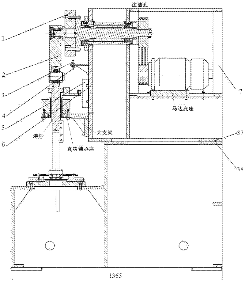
[0024] Such as Figure 1-Figure 10 As shown, this embodiment includes: an eccentric wheel main shaft assembly 1, a swing rod assembly 2, a proximity switch 3, a bracket 4, a length sensor 5, a box body 6 and a box basket 7, wherein: the eccentric wheel main shaft assembly 1 is located at the swing rod assembly 2 Above and connected to it, the swing rod assembly 2 is located on the lower side of the eccentric wheel main shaft assembly 1 and connected to it, the proximity switch 3 is located directly below the eccentric wheel main shaft assembly 1 and connected to the bracket 4, and the bracket 4 is located directly ...


PUM


Abstract

The invention relates to an axial load fatigue testing device in the technical field of auto parts and components manufacture. The axial load fatigue testing device comprises an eccentric wheel spindle assembly, a swing link assembly, a proximity switch, a bracket, a length sensor, a box body and a box basket. The invention is suitable for an axial fatigue test of a flywheel web plate stamping piece which is subjected to an adjustable load with cyclic stress in room-temperature air; and the frequency for the test can be selected from a range of 10-30 Hz. A testing method comprises the steps: a motor is started; when a big and a small belt wheels with certain revolution speed drive the eccentric wheel spindle assembly to rotate, the swing link assembly and a connecting bar freely operate in a linear bearing up and down; a certain load is applied to a piece to be tested (according to the requirement of a modeling test) with a certain loading frequency; and a back and forth cyclic fatigue test is carried out to finally examine whether the piece to be tested satisfies with relevant requirements of an axial load fatigue test or not.

Description

technical field [0001] The invention relates to a device and a method in the technical field of auto parts manufacturing, in particular to an axial load fatigue test device and a test method thereof. Background technique [0002] At present, domestic fatigue tests on automatic transmission flywheels are mainly carried out in some university test centers or some foreign test institutions. However, since the test equipment of these test institutions is not used for automobile flywheels, the price of the equipment and the test cost are It is very expensive, and it is often necessary to adjust the workbench of the equipment according to the characteristics of the test piece during the test, and it is not specially designed for the flywheel. [0003] After searching the existing technology, it is found that Chinese patent application number 201010297385.4 records a "new axial fatigue testing machine". This technology is suitable for an axial fatigue testing machine for automobile...

Claims


Application Information

Patent Timeline
Patent Type & Authority Applications(China)
IPC IPC(8): G01N3/28G01N3/02
Inventor 迟令山
Owner SHANGHAI AUTOMOBILE GEAR WORKS
Why Eureka
Try Eureka