Apparatus and method for measuring electron temperature of plasma in gas based on laser induction

A plasma and laser-induced technology, applied to the temperature measurement of moving fluid, thermal excitation analysis, material excitation analysis, etc., can solve the problems of plasma state influence, large measurement error, easy contamination of the probe surface, etc., and achieve measurement error Low, high precision effect

Active Publication Date: 2011-11-23
HARBIN INST OF TECH
View PDF4 Cites 20 Cited by
  • Summary
  • Abstract
  • Description
  • Claims
  • Application Information

AI Technical Summary

Problems solved by technology

[0003] The present invention aims to solve the existing problems of the existing devices and methods for measuring plasma electron temperature that the detection probe is inserted into the plasma, which affects the state of the plasma, and the surface of the probe is easily polluted, resulting in a large measurement error. problem, and the proposed laser-induced measurement of the plasma electron temperature device and its measurement method in the gas

Method used


Image

  • Apparatus and method for measuring electron temperature of plasma in gas based on laser induction
  • Apparatus and method for measuring electron temperature of plasma in gas based on laser induction
  • Apparatus and method for measuring electron temperature of plasma in gas based on laser induction

Examples


specific Embodiment approach 1

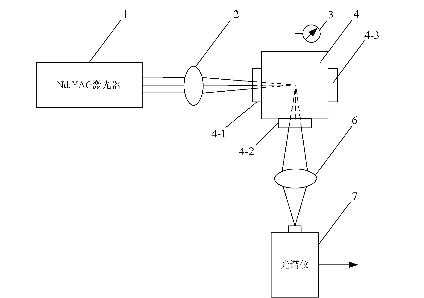
[0021] Specific implementation mode one: combine figure 1 Illustrate this embodiment, the device for measuring plasma electron temperature in gas based on laser induction described in this embodiment, it includes Nd:YAG laser 1, focusing lens 2, airtight gas chamber 4, converging lens 6 and spectrometer 7; The gas chamber 4 is filled with the gas to be measured; the center of the three sides of the airtight chamber 4 is respectively embedded with a first quartz light-transmitting window 4-1, a second quartz light-transmitting window 4-2 and a third quartz light-transmitting window. Optical window 4-3; the laser beam emitted by the laser outlet of the Nd:YAG laser 1 passes through the focusing lens 2 and the first quartz light-transmitting window 4-1 and converges to the inner center point of the airtight air chamber 4; the said The distance between the inner central point of the airtight air chamber 4 and the focus lens 2 is the focal length of the focus lens 2; The central a...

specific Embodiment approach 2

[0022] Specific implementation mode two: combination figure 1 Describe this embodiment, the difference between this embodiment and the specific embodiment is that it also increases the barometer 3; the air pressure collection end of the barometer 3 extends into the airtight chamber 4 inside; It communicates with the gas to be measured inside the airtight chamber 4 . Other compositions and connection methods are the same as those in Embodiment 1. The purpose of increasing the barometer 3 is to monitor the air pressure inside the airtight chamber 4 .

specific Embodiment approach 3

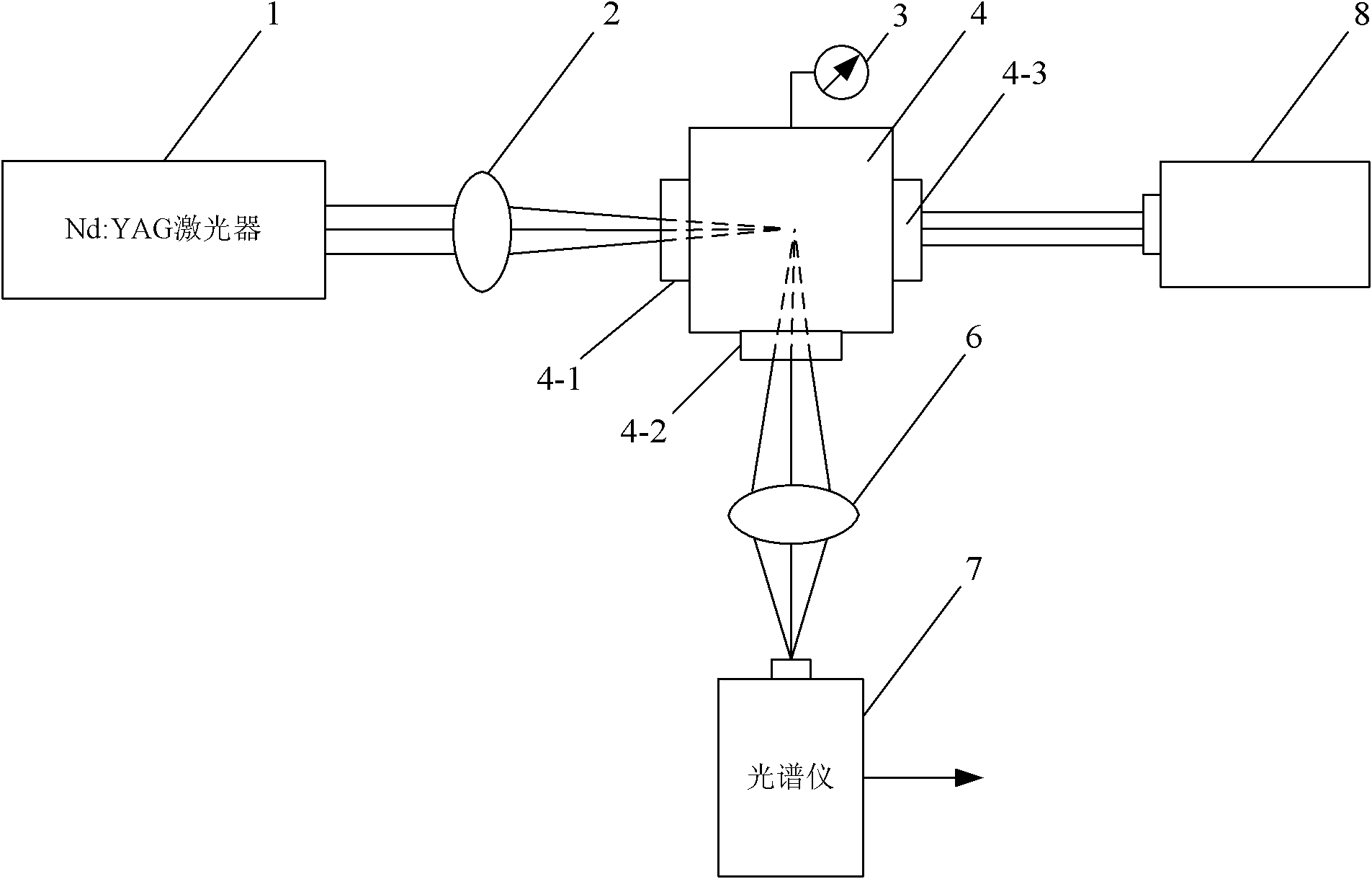
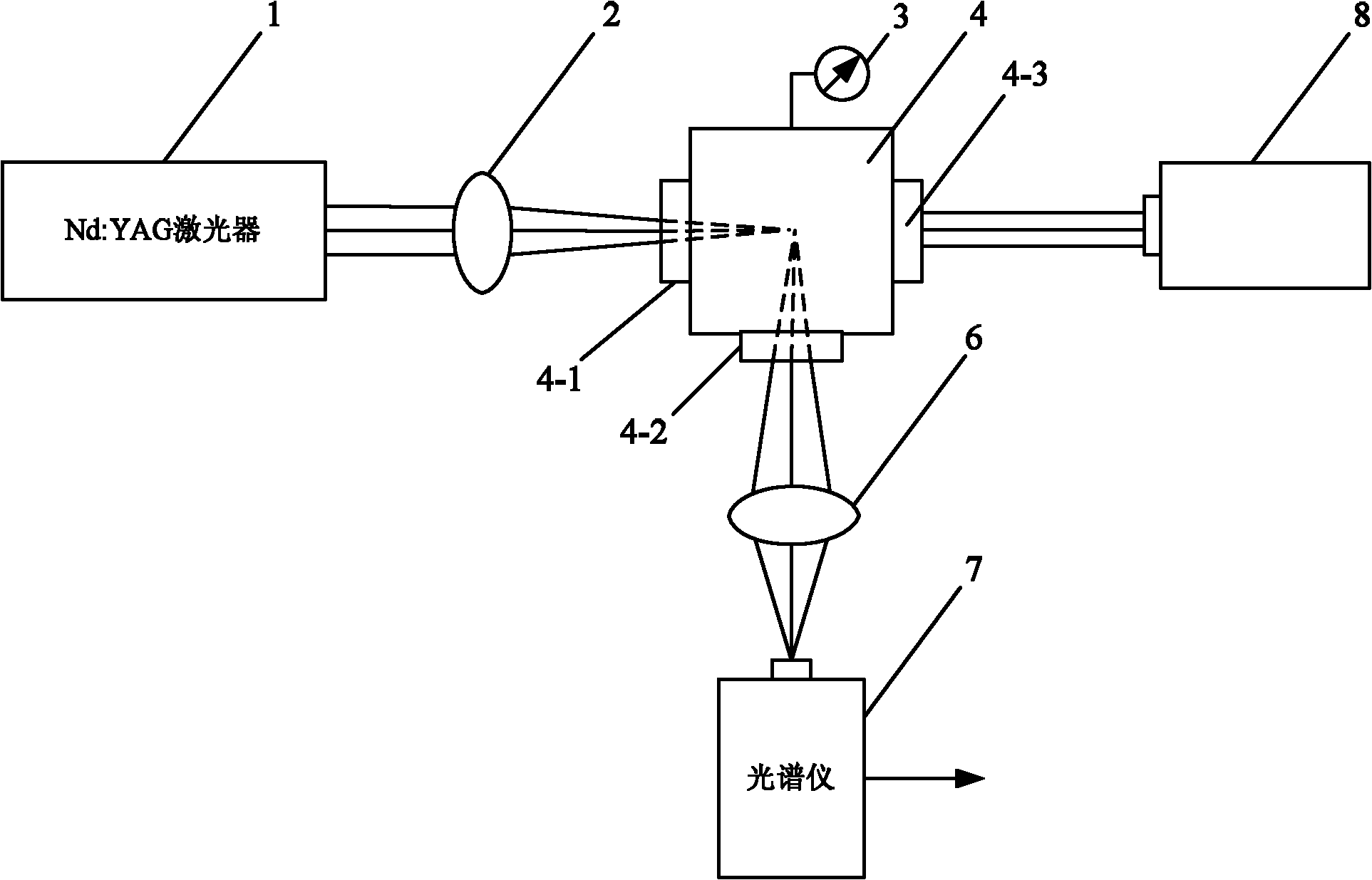
[0023] Specific implementation mode three: combination figure 2 Describe this embodiment, the difference between this embodiment and the second embodiment is that it also increases the afterglow collection device 8; the afterglow collection device 8 is installed on the outside of the third quartz light-transmitting window 4-3; The central axis of the light collecting window of the collecting device 8 is on the same axis as the central axis of the third quartz light-transmitting window 4-3. Other compositions and connection methods are the same as those in the second embodiment. The purpose of adding the afterglow collection device 8 is to eliminate the influence of the scattered light generated by the laser beam on the plasma spectrum.


PUM

PropertyMeasurementUnit
lengthaaaaaaaaaa

Abstract

The invention relates to an apparatus and a method for measuring the electron temperature of plasma in gas based on laser induction, and relates to an apparatus and a method for measuring the electron temperature of plasma. In prior plasma electron temperature measuring apparatuses and methods, probes are inserted into plasma, such that the status of plasma is influenced; surfaces of probes are easy to be polluted, such that relatively large errors are generated. With the apparatus and the method, the problems can be solved. Laser beams emitted from an emission port of an Nd: YAG laser penetrate through a focusing lens and a first quartz light inlet window, and are converged on an inner central point of an enclosed air chamber. Spectral lines emitted from a second quartz light inlet window pass through a converging lens, and are converged on a spectrum collection terminal of a spectrometer. The observation method comprises the steps that: one, the enclosed air chamber is filled with air; two, plasma are generated by the induction of the laser; three, plasma emission spectra are collected by the spectrometer; four, atomic lines are selected; five, electron temperature is obtained through calculation. The method has characteristics of low measuring error and high precision.

Description

technical field [0001] The invention relates to a device for measuring plasma electron temperature and a measuring method thereof. Background technique [0002] The electron temperature of the plasma is an important parameter of the plasma, which is used to characterize the activity of the particles in the plasma. The traditional way to measure plasma electron temperature is to use Langmuir probe measurement method. This method needs to insert the probe into the plasma, which will not only affect the state of the plasma, but also the surface of the probe is easily polluted, which will introduce a large measurement error. Contents of the invention [0003] The present invention aims to solve the existing problems of the existing devices and methods for measuring plasma electron temperature that the detection probe is inserted into the plasma, which affects the state of the plasma, and the surface of the probe is easily polluted, resulting in a large measurement error. Pro...

Claims


Application Information

Patent Timeline
Patent Type & Authority Applications(China)
IPC IPC(8): G01N21/73G01K13/02G01K13/024
Inventor 于欣李晓晖孙锐陈德应樊荣伟彭江波
Owner HARBIN INST OF TECH
Why Eureka
Try Eureka