
Consumed power regulating system and method

A technology for power consumption and system regulation, applied in the field of power management of multi-board systems

Inactive Publication Date: 2011-11-23
INVENTEC CORP
View PDF6 Cites 0 Cited by
  • Summary
  • Abstract
  • Description
  • Claims
  • Application Information

AI Technical Summary

Problems solved by technology

Furthermore, the control by software requires the program to estimate the power usage status of the system. In addition to being prone to errors, it takes a long time for the software program to make a decision.

Method used


Image

  • Consumed power regulating system and method
  • Consumed power regulating system and method
  • Consumed power regulating system and method

Examples


Embodiment Construction

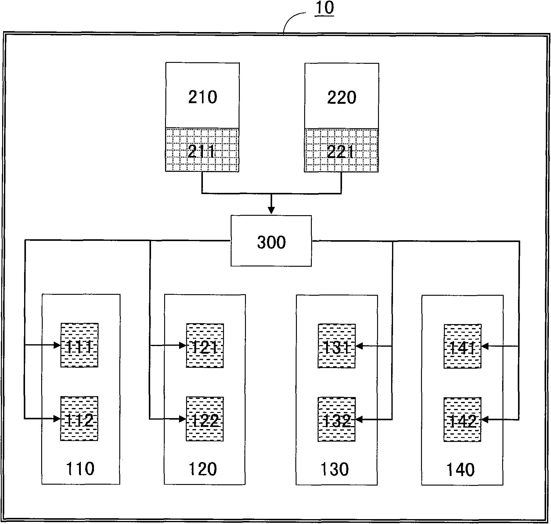
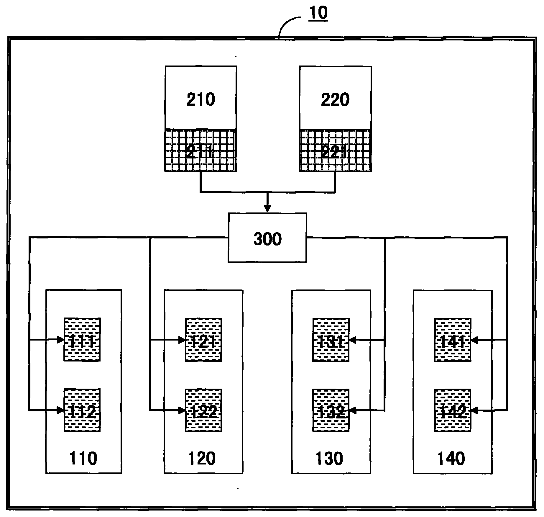
[0022] Please refer to figure 1 , is a block diagram of an embodiment of the power consumption regulation system of the present invention. The power consumption adjustment system of the present invention is set in the server system 10 and includes a plurality of motherboards 110 - 140 , power supply units 210 and 220 , and a logic judgment circuit 300 . The motherboards 110 - 140 respectively have processing units 111 , 112 , processing units 121 , 122 , processing units 131 , 132 , and processing units 141 , 142 . The processing units 111, 112, the processing units 121, 122, the processing units 131, 132, and the processing units 141, 142 use the output of the logic judgment circuit 300 to switch an operating frequency for data calculation, and operate at this operating frequency. different states.

[0023] The power supply units 210 , 220 provide power for the mainboards 110 - 140 and the server system 10 , and provide power to the mainboards 110 - 140 through a logic judg...


PUM


Abstract

The invention provides a consumed power regulating system and method. The system comprises a plurality of mainboards, two power supply units and a logic judgment circuit. By means of the hardware judgment manner of the logic judgment circuit, the working frequency of the mainboards are switched automatically to regulate the consumed power in accordance with the consumed power capable of being supplied by the power supply units so as to keep a server system operate normally.

Description

technical field [0001] The present invention relates to a multi-mainboard system, and in particular to power management of a multi-mainboard system. Background technique [0002] In the known electronic devices or systems, the power management is usually performed by software in accordance with specifications formulated by various specifications such as advanced configuration and power interface. Power management by software is mainly based on a software program, which estimates possible system power usage states according to different central control unit (CPU) utilization rates, and adjusts different system power usage states. However, using software programs for control cannot reflect the actual operating conditions of the current system to the system power management in real time. Furthermore, the control by software requires the program to estimate the power usage status of the system. In addition to being prone to errors, it takes a long time for the software program ...

Claims


Application Information

Patent Timeline
Patent Type & Authority Applications(China)
IPC IPC(8): G06F1/30
Inventor 王煌清陈建安
Owner INVENTEC CORP
Features
  • Generate Ideas
  • Intellectual Property
  • Life Sciences
  • Materials
  • Tech Scout
  • Unparalleled Data Quality
  • Higher Quality Content
  • 60% Fewer Hallucinations
Learn More