Battery charging control system and battery charging control circuit

A battery charging and charging control technology, which is applied to battery circuit devices, circuit devices, current collectors, etc., can solve the problems of current consumption, occupying a large area, and large resistance value of the voltage divider resistor, so as to reduce the current consumption, The effect of saving power and reducing the number of repeated charging

Active Publication Date: 2011-11-23
WUXI ZGMICRO ELECTRONICS CO LTD
View PDF3 Cites 2 Cited by
  • Summary
  • Abstract
  • Description
  • Claims
  • Application Information

AI Technical Summary

Problems solved by technology

[0005] This approach has two disadvantages. One is that the voltage dividing resistor will consume a certain amount of current, which is on the order of several microamperes; the other is that if you want to reduce the current consumed by the voltage dividing resistor, the resistance value of the selected resistor will be very large. , usually a few megaohms, occupy a large area and increase the cost

Method used


Image

  • Battery charging control system and battery charging control circuit
  • Battery charging control system and battery charging control circuit
  • Battery charging control system and battery charging control circuit

Examples


Embodiment Construction

[0020] The detailed description of the present invention directly or indirectly simulates the operation of the technical solution of the present invention mainly through programs, steps, logic blocks, processes or other symbolic descriptions. In the ensuing description, numerous specific details are set forth in order to provide a thorough understanding of the present invention. Rather, the invention may be practiced without these specific details. These descriptions and representations herein are used by those skilled in the art to effectively convey the substance of their work to others skilled in the art. In other words, for the purpose of avoiding obscuring the present invention, well-known methods and procedures have not been described in detail since they have been readily understood.

[0021] Reference herein to "one embodiment" or "an embodiment" refers to a particular feature, structure or characteristic that can be included in at least one implementation of the pres...


PUM


Abstract

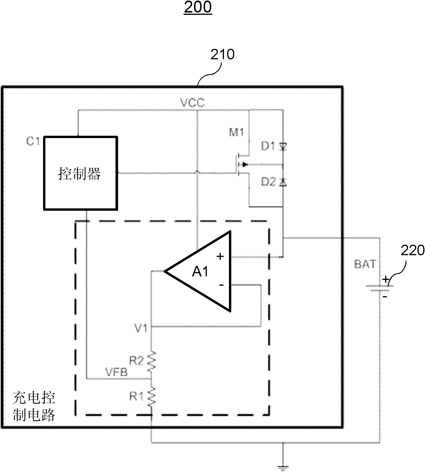
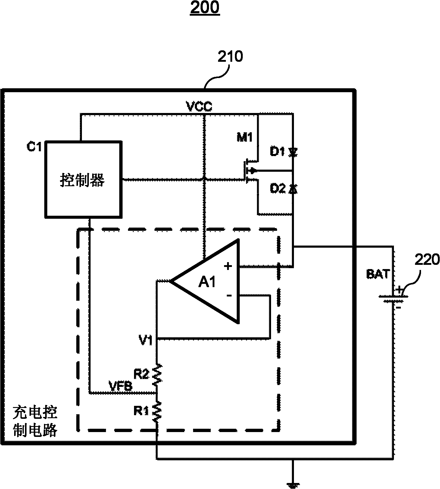
The invention provides a battery charging control system, which comprises a battery and a charging control circuit, wherein the charging control circuit comprises an operational amplifier, a first divider resistor, a second divider resistor and a controller; the operational amplifier is supplied with power by a charging power supply; a first input end of the operational amplifier is connected with one end of the battery, and a second input end of the operational amplifier is connected with an output end of the operational amplifier; the first divider resistor and the second divider resistor are connected in series between the output end of the operational amplifier and the other end of the battery; and the intermediate node of the first divider resistor and the second divider resistor provides a feedback voltage for the controller. By the battery charging control system, quiescent currents consumed by the battery can be as small as possible in a standby state.

Description

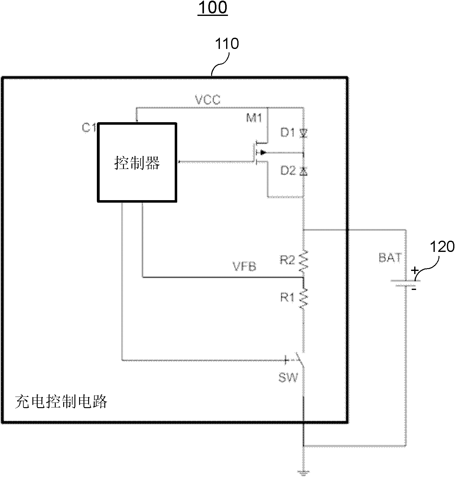
【Technical field】 [0001] The invention relates to the field of electronic circuits, in particular to a battery charging control system and a battery charging control circuit. 【Background technique】 [0002] In the charger application, when the battery is fully charged, it will enter the standby (standby) state. Since the voltage of the battery needs to be detected to determine whether to recharge, it is hoped that the quiescent current consumed by the battery should be as small as possible. When the existing charger chip enters the standby state, the usual practice is to use a string of voltage dividing resistors to detect the voltage of the battery. [0003] Such as figure 1 As shown, it shows a schematic diagram of an existing battery charging control system 100. The system 100 includes a battery charging control circuit 110 and a rechargeable battery (BAT) 120. The battery charging control circuit 110 includes a controller C1, The transistor M1, the first diode D1, the ...

Claims


Application Information

Patent Timeline
IPC IPC(8): H02J7/00
Inventor 田文博尹航牛旭花王钊
Owner WUXI ZGMICRO ELECTRONICS CO LTD
Why Eureka
Try Eureka