
Armature, starting motor and method for manufacturing armature

An armature and armature shaft technology, which is applied to electric components, electrical components, electromechanical devices, etc., can solve problems such as large changes, accelerated motor temperature rise, deformation of bushing 126, etc., to reduce expansion and internal stress, The effect of reducing internal stress and reducing the interference volume

Inactive Publication Date: 2011-11-23
PRESTOLITE ELECTRIC BEIJING
View PDF7 Cites 2 Cited by
  • Summary
  • Abstract
  • Description
  • Claims
  • Application Information

AI Technical Summary

Problems solved by technology

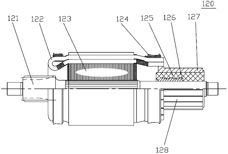
from figure 2 It can be seen that the matching structure between the commutator 128 and the armature shaft 121 is: the bushing 126 embedded in the commutator 128 is fitted on the armature shaft 121 with an interference fit. The impact of accuracy varies greatly, which easily leads to excessive interference volume, which makes the bushing 126 deform and generates internal stress between the bushing 126 and the insulating packing 125 that cannot be released immediately. This internal stress is released during the working process of the starter motor, which will cause As a result, the radial runout of the contact surface between the commutator and the brush becomes larger, thereby accelerating the temperature rise of the motor. If it is light, it will cause noise in the working process and shorten the life of the starter. Dispersed machine failure

Method used


Image

  • Armature, starting motor and method for manufacturing armature
  • Armature, starting motor and method for manufacturing armature
  • Armature, starting motor and method for manufacturing armature

Examples


no. 1 example

[0056] refer to figure 2 and refer to image 3 , the armature 120 of the present invention includes: an armature shaft 121, an armature wire 122, an armature core lamination 123, a binding ring 124 and a commutator 128, and the commutator is axially penetrated and arranged on the armature shaft 121 as The armature wire 122 shunts the power supply, the armature iron core lamination 123 is axially penetrated and fixed on the armature shaft 121, the armature wire 122 is inserted in the armature iron core lamination 123 and connected with the commutator, and the binding ring 124 is connected to the electric The pivot line 122 acts as a radial fixation. The commutator 128 includes an insulating filler 125, a bushing 126, and a plurality of commutator segments 127 that are evenly distributed around the axis of the armature shaft 121 and are not connected to each other. The sleeve 126 is fixed as a whole, and the bushing 126 is in interference fit with the armature shaft 121 to en...

no. 2 example

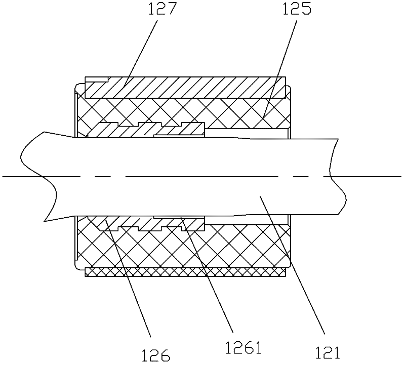
[0059] refer to Figure 4 A partial sectional view of the armature of the second embodiment of the present invention. In this embodiment, the structure of the armature is substantially the same as that in the first embodiment. The difference is that in this embodiment, the annular groove 1261 is arranged on the lining The annular groove 1261 extends from the left end surface of the bushing 126 to the middle of the bushing along the bushing axis but does not go through the whole bushing.

[0060] Regarding other structures of this embodiment, since they are the same as those of the first embodiment, details will not be repeated here.

no. 3 example

[0062] refer to Figure 5 A partial cross-sectional view of the armature of the third embodiment of the present invention. In this embodiment, the structure of the armature is roughly the same as that in the first embodiment. The difference is that in this embodiment, the number of annular grooves is Two, one annular groove 1261 is arranged on the inner wall of the bushing away from the armature core laminations, and the other annular groove 1262 is arranged on the inner wall of the bushing near the armature iron core laminations.

[0063] Regarding other structures of this embodiment, since they are the same as those of the first embodiment, details will not be repeated here.


PUM


Abstract

The invention discloses an armature and a starting motor containing the armature, and also discloses a method for manufacturing the armature, relating to the technical field of motors. The armature comprises an armature shaft, an armature line, an armature core lamination and a commutator, wherein the armature core lamination is fixed on the armature shaft; the armature line is inserted into the armature core lamination and connected with the commutator; the commutator comprises multiple commutating segments which are uniformly distributed around the axis of the armature shaft and not connected with each other; a bush is arranged on the armature shaft in an interference fit mode; the commutating segments and the bush are fixed into a whole; the inner wall of the bush is provided with at least one annular groove; and the bush forms fit clearance between the annular groove position and the armature shaft. According to the invention, the annular groove arranged on the inner wall of the bush can reduce the internal stress of the armature, thus the smooth working condition of the surface of the commutator can be ensured, the service life of a starter can be prolonged and the possibility of the starter failure can be reduced.

Description

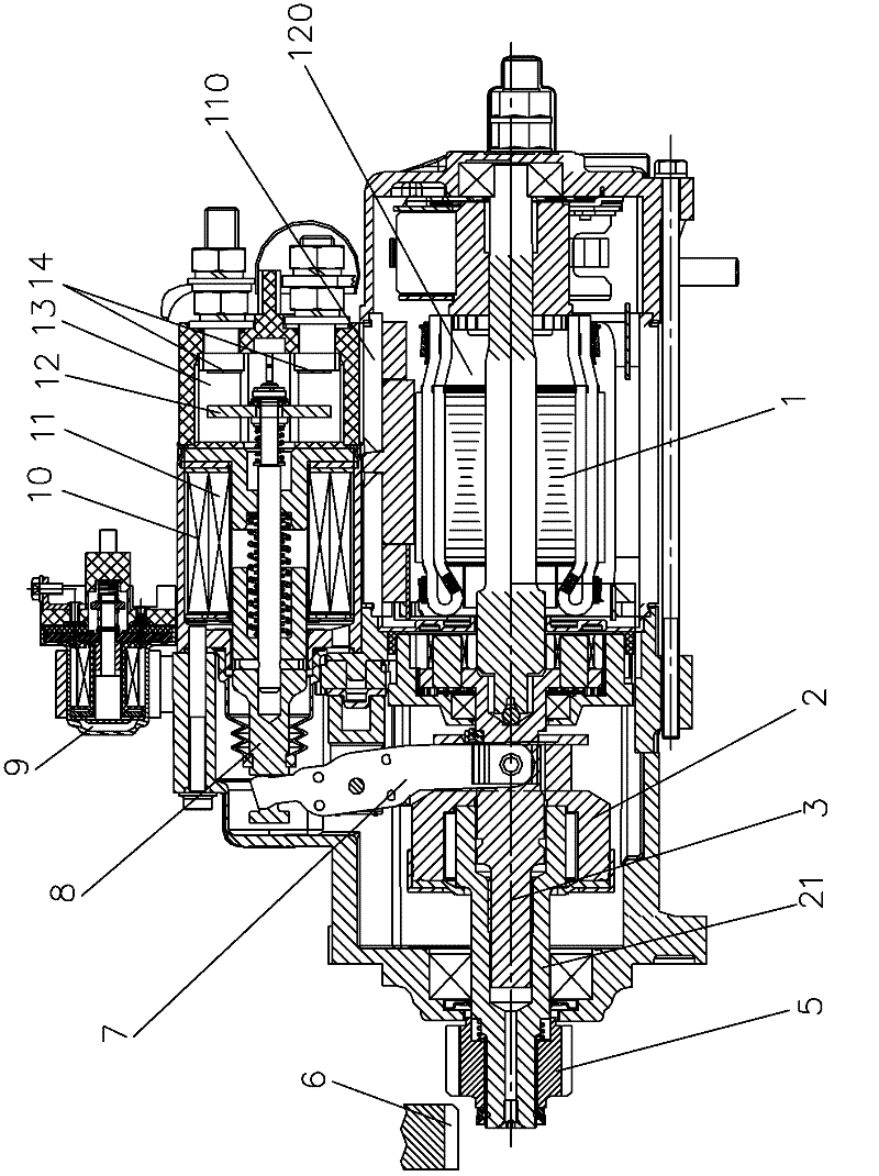
technical field [0001] The invention relates to a starter motor, in particular to an armature of the starter motor and a method for making the armature. Background technique [0002] The existing starter motor structure is as follows figure 1 As shown, it includes a motor 1 that generates rotational force and is composed of a stator 110 and an armature 120, a roller type one-way clutch 2 that is splined with a drive shaft 3 of a reduction gear connected to the motor 1, and a roller type one-way clutch 2 As soon as the clutch 2 integrally moves on the gear shaft 21 along its axial direction, the driving gear 5, the relay 9, and the contacts of the relay 9 are closed, the current flows into the pull coil 11 and the holding coil 10, and attracts the moving iron core under the magnetic field generated by it. 8 Push the movable contact plate 12 to move to the electromagnetic switch 13 on the side of the static contact 14. Along with the movement of moving iron core 8, shift for...

Claims


Application Information

Patent Timeline
Patent Type & Authority Applications(China)
IPC IPC(8): H02K1/22H02K7/10H02K15/02
Inventor 李想朱鸿
Owner PRESTOLITE ELECTRIC BEIJING
Learn More