
Motor device

A technology of motors and magnets, applied in the field of DC motor devices, can solve the problems of affecting the rotating force and speed of the rotor core 121, increasing the cost of production and assembly, reducing the magnetic absorption effect of the magnet, achieving a breakthrough in design concepts, reducing magnetic energy loss, The effect of increasing the number of coils or wire diameter

Inactive Publication Date: 2011-11-23
CHESHIRE ELECTRIC COMPANY
View PDF7 Cites 2 Cited by
  • Summary
  • Abstract
  • Description
  • Claims
  • Application Information

AI Technical Summary

Problems solved by technology

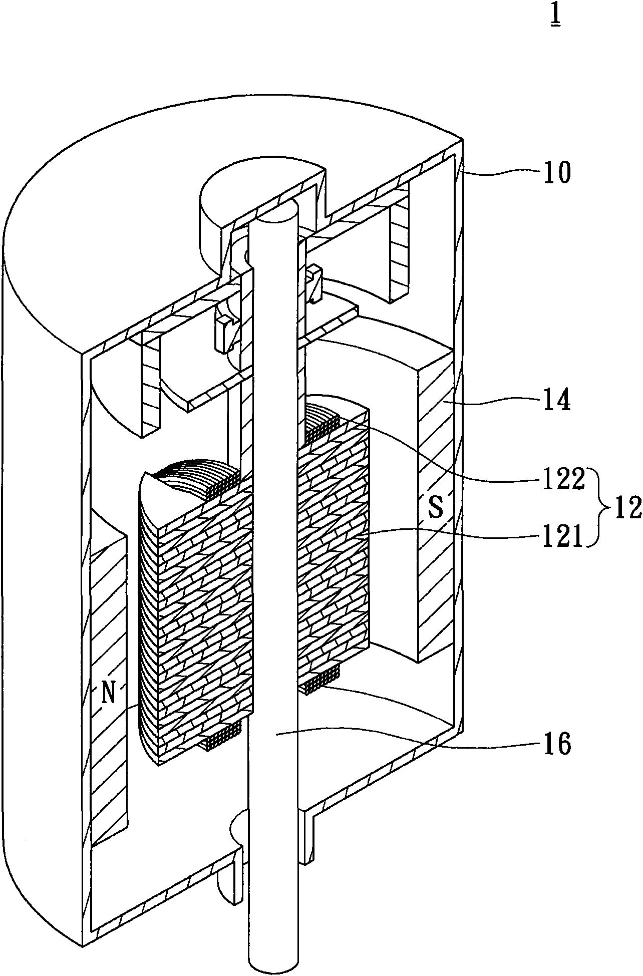
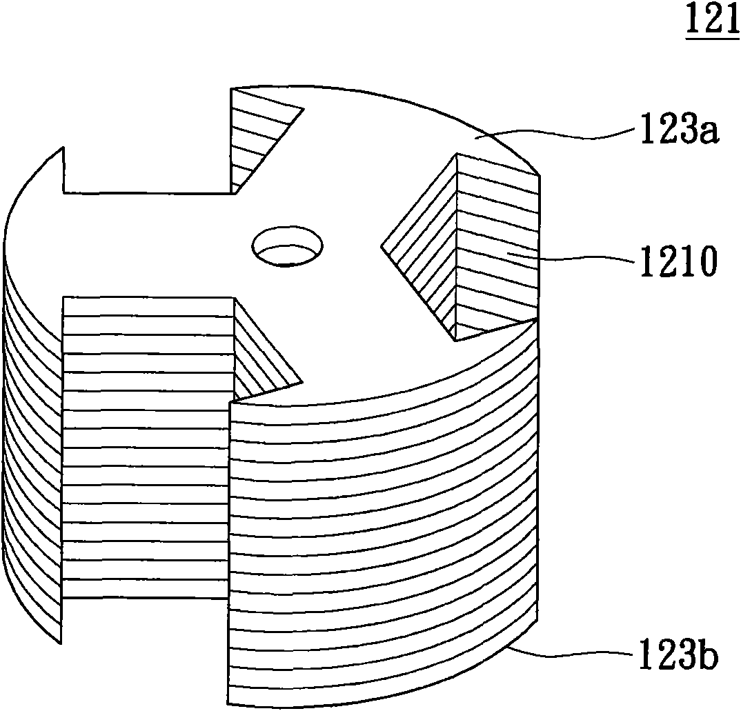
[0004] However, the structure of this rotor core 121 will have the following problems: (1) The rotor core 121 is made of a plurality of silicon steel sheets 1210 stacked to form a magnet, which is extremely time-consuming to manufacture and reduces the magnetic properties of the raw material
(2) When the rotor core 121 is wound with coils, the wire wraps on the upper surface and the lower surface will reduce the magnetic absorption effect of the magnet, thereby affecting the rotational force and speed of the rotor core 121
(3) In terms of production, only the rotor core 121 with a constant cross-section shape can be produced. If a rotor core 121 with a non-uniform cross-section shape is to be produced, more stamping die sets are required to cooperate, resulting in an increase in production and assembly costs.

Method used


Image

  • Motor device
  • Motor device
  • Motor device

Examples


Embodiment Construction

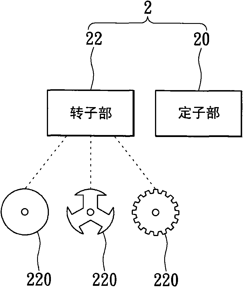
[0046] Please refer to image 3 . image 3 It is a structural schematic diagram of the motor device of the embodiment of the present invention. The motor device 2 of this embodiment includes a stator part 20 and a rotor part 22 . The structural design of the motor device 2 is that the rotor part 22 is arranged on the inner ring of the stator part 20. In this way, after the motor device 2 is energized, the rotor part 22 will interact magnetically with the stator part 20, and the inner ring of the stator part 20 Make a turn. In the foregoing cases, the motor device 2 may be a DC stepping motor, a DC series motor, a DC brushless motor or a DC brushed motor.

[0047] Refer again image 3 . The rotor part 22 includes a rotor core 220, and the appearance of the rotor iron core 220 can be designed as a cylindrical rotor iron core, a radial rotor iron core or a gear-shaped rotor iron core, however, the aforementioned various rotor iron core 220 shapes are embodiments of the prese...


PUM


Abstract

The invention discloses a motor device, comprising a stator part and a rotor part, wherein the rotor part is arranged in an inner ring of the stator part; magnetic action is generated between the rotor part and the stator part so that the rotor part rotates in the inner ring of the stator part; the rotor part comprises a rotor iron core; the rotor iron core is integrally formed from magnetic powder through a powder metallurgy process; the magnetic powder is a soft magnetic material with a core-shell structure; and the soft magnetic material comprises a core main body for supplying magnetic force and a shell layer for supplying connection intensity. According to the motor device disclosed by the invention, the rotor part is structurally improved; therefore, the rotor part is not influenced by a coil; the winding turn number or wire diameter can be increased; the motor torque and rotation speed can be increased; the magnetic energy loss can be reduced effectively; on the premise of having the same unit output power, the size of the motor is reduced; and the design concept of the traditional motor rotor is broken through.

Description

technical field [0001] A motor device, especially a direct current motor device. Background technique [0002] refer to figure 1 . figure 1 It is a three-dimensional sectional view of a conventional motor device. The conventional motor device 1 is provided with a stator part 14 and a rotor part 12 inside the housing 10 , the rotor part 12 has a rotor core 121 , and the rotor core 121 is provided with a rotor coil 122 . The axis of the rotor core 121 provides a rotating shaft 16 , so that the rotating shaft 16 can be driven by the rotating rotor core 121 . [0003] Cooperate figure 1 ,refer to figure 2 . figure 2 It is a three-dimensional schematic diagram of a rotor core of a conventional motor device. The rotor core 121 is formed by punching and stacking a plurality of silicon steel sheets 1210 . The rotor core 121 is formed by stacking a plurality of silicon steel sheets 1210. The upper surface and the lower surface of the rotor core 121 are respectively placed w...

Claims


Application Information

Patent Timeline
Patent Type & Authority Applications(China)
IPC IPC(8): H02K1/27
Inventor 王金龙黄鸿智
Owner CHESHIRE ELECTRIC COMPANY
Learn More