Transmitter terminal and receiver terminal

A transmitter and receiver technology, applied in transmission systems, digital transmission systems, adjustment of transmission methods, etc., can solve problems such as rearrangement

Active Publication Date: 2011-11-23
PANASONIC CORP
View PDF12 Cites 0 Cited by
  • Summary
  • Abstract
  • Description
  • Claims
  • Application Information

AI Technical Summary

Problems solved by technology

Reordering may occur if short packets arrive at such a router from a specific transmitter terminal

Method used


Image

  • Transmitter terminal and receiver terminal
  • Transmitter terminal and receiver terminal
  • Transmitter terminal and receiver terminal

Examples


Embodiment 1

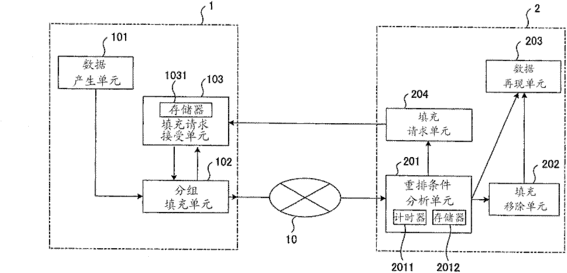
[0041] figure 1 is a block diagram showing a schematic structure of a transmitter terminal and a receiver terminal according to Embodiment 1 of the present invention.

[0042] exist figure 1 Among them, the transmitter terminal 1 includes a data generating unit 101 , a packet filling unit 102 and a filling request accepting unit 103 . The data generating unit 101 encodes data of audio, video, etc., and generates packets. Packet padding unit 102 pads packets to a specific packet length and transmits the packets to network 10 . The padding request accepting unit 103 receives the padding request packet and instructs the packet padding unit 102 to pad the packet to an appropriate length. The filling request accepting unit 103 has a memory 1031 for data storage.

[0043] In order to encode the video, the data generation unit 101 performs an encoding process on each specific data unit. Specifically, the data generating unit 101 performs encoding processing in units of one scr...

Embodiment 2

[0059] Figure 5 is a block diagram showing schematic configurations of a transmitter terminal and a receiver terminal according to Embodiment 2 of the present invention. exist Figure 5 , denoted by the same reference numerals as previously referred to figure 1 The units described are common to the units. In Embodiment 1 described above, the transmitter terminal 1 decides whether or not stuffing needs to be performed based on the stuffing request transmitted from the receiver terminal 2 . The difference between Embodiment 2 and Embodiment 1 is that whether filling is required is determined in transmitter terminal 1A.

[0060] exist Figure 5 , the rearrangement prediction unit 501 of the transmitter terminal 1A predicts whether rearrangement will occur in the network 10. Packet stuffing unit 502 and figure 1 The packet stuffing unit 102 in has the same function, and the difference from the packet stuffing unit 102 is that the rearranging prediction unit 501 provides s...


PUM


Abstract

This invention relates to transmitter and receiver terminals that transmit and receive real-time streaming data via a network. This invention achieves reduction of ultimate transmission delay time by avoiding the occurrences of reorders themselves. In the transmitter terminal (1), a padding request accepting unit (103) receives a padding request packet transmitted by the receiver terminal (2). Based on an instruction from the padding request accepting unit (103), a packet padding unit (102) pads a packet, which has been generated by a data generating unit (101), such that the packet length of the packet is equal to or greater than a particular length. The packet padding unit (102) then transmits the packet as padded to a network (10). In the receiver terminal, a reorder condition analyzing unit (201) analyzes the reorder-occurrence condition of the packet received from the network. Based on an analysis result received from the reorder condition analyzing unit (201), a padding requesting unit (204) generates and transmits a padding request packet to the transmitter terminal. A data reproducing unit (203) reproduces the packet received by the reorder condition analyzing unit (201).

Description

technical field [0001] The present invention relates to a transmitter terminal for transmitting streaming data such as audio and video in real time through a network such as the Internet performing packet communication, and a receiver terminal for receiving streaming data transmitted from the transmitter terminal. Background technique [0002] Figure 7 is a diagram showing usage states of the above-mentioned transmitter terminal and receiver terminal. exist Figure 7 , the transmitter terminal 11 divides real-time streaming data such as audio and video into packets for transmission to the receiver terminal 12 through the network 10 . [0003] By performing link trunking or introducing multiple encryption devices, a network such as the Internet can be set to a wider bandwidth, and a VPN (Virtual Private Network) router can be accelerated. Figure 8 is a diagram showing an example. exist Figure 8 , routers (repeaters) 801 , 802 , and 803 are located in the network interve...

Claims


Application Information

Patent Timeline
IPC IPC(8): H04L12/56
CPCH04L1/0008H04L12/4641H04W28/04
Inventor 村本卫一
Owner PANASONIC CORP
Why Eureka
Try Eureka