
Eccentric type curved weir intercepting well

An interception well and eccentric technology, applied in the field of interception wells, can solve problems such as easy deposition, large buried depth, poor drainage of rectangular weirs, etc., and achieve the effect of increasing discharge capacity and reducing deposition

Inactive Publication Date: 2013-01-23
ZHEJIANG UNIV
View PDF4 Cites 0 Cited by
  • Summary
  • Abstract
  • Description
  • Claims
  • Application Information

AI Technical Summary

Problems solved by technology

However, in some cases, for example, the constant water level of rivers and other water bodies near cities is relatively high, and the heightening of the embankment and the terrain along the river has resulted in the deep burial of the original confluence pipes and canals that directly discharge into the river, even reaching more than 10 meters. In order to reduce construction difficulty and cost, the interception main pipe with a relatively small buried depth is often used for the closure of the original straight-line combined pipe and canal. Therefore, during the closure reconstruction process, the elevation of the intercepted sewage outlet pipe is higher than the elevation of the water inlet pipe and canal. well
The sewage in this kind of interception well is under pressure. The type of interception well is generally designed as a rectangle. The inlet pipe is located in the middle of the interception well. Poor drainage during periods of heavy rainfall

Method used


Image

  • Eccentric type curved weir intercepting well
  • Eccentric type curved weir intercepting well
  • Eccentric type curved weir intercepting well

Examples


Embodiment Construction

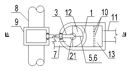
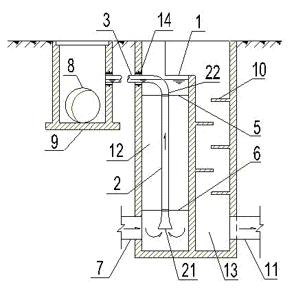
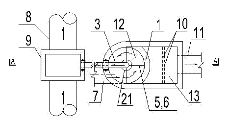
[0018] Such as figure 1 and figure 2 As shown, a curved overflow weir 1 is vertically arranged in the intercepting well of the present invention, and the curved overflow weir 1 separates the intercepting well into an intercepting well chamber 12 and an overflow well chamber 13 .

[0019] Wherein, the cross section of the intercepting well chamber 12 is circular, so that the incoming water can form a swirling flow in the intercepting well chamber. The lower end of the intercepting well chamber 12 is provided with a sewage inlet 7 , and the upper end of the intercepting well chamber 12 is provided with an intercepting sewage outlet 14 .

[0020] Such as figure 1 , 3 , 4, and 5, the outer inner wall 71 of the sewage inlet 7 is tangent to the inner wall of the interception well chamber 12, and the inner diameter of the sewage inlet 7 is less than half of the inner diameter of the interception well chamber 12, so that the sewage inlet is an eccentric water inlet mode, In ord...


PUM


Abstract

The invention discloses an eccentric type curved weir intercepting well. The intercepting well is characterized in that a curved overflow weir is vertically arranged in a vertical intercepting well; the curved overflow weir separates the intercepting well into an intercepting well chamber and an overflow well chamber; the intercepting well chamber has a circular cross section; the lower end of the intercepting well chamber is provided with a sewage inlet; the upper end of the intercepting well chamber is provided with an intercepted sewage outlet; the outer inner wall of the sewage inlet is tangent to the inner wall of the intercepting well chamber; the inner diameter of the sewage inlet is less than a half of the inner diameter of the intercepting well chamber; a vertical intercepted sewage outlet pipe is vertically arranged in the intercepting well chamber; a lower end opening of the vertical intercepted sewage outlet pipe is in the elevation range of the top end and bottom end of the sewage inlet; the geometric center of the lower end opening of the vertical intercepted sewage outlet pipe coincides with the central axis of the intercepting well chamber; and an upper end openingof the vertical intercepted sewage outlet pipe is communicated with the intercepted sewage outlet by a horizontal intercepted sewage outlet pipe. By the adoption of the invention, deposits in the intercepting well can be reduced and the eccentric type curved weir intercepting well can discharge redundant flow as quickly as possible when the rainwater quantity is large.

Description

technical field [0001] The invention relates to an intercepting well in an intercepting combined drainage system, in particular to a pressure-bearing intercepting well whose elevation of the sewage intercepting outlet pipe is higher than that of the water inlet pipe. Background technique [0002] The urban direct combined drainage system will cause serious water and natural environment pollution. In order to protect the environment and reduce pollution, the common countermeasure is to transform it into an intercepting combined drainage system, and the intercepting well is an important subsidiary structure. The traditional interception wells are all gravity flow interception wells, the elevation of the sewage interception outlet pipe is lower than the elevation of the water inlet pipe, and the water flow in the interception well is in the state of gravity flow. However, in some cases, for example, the constant water level of rivers and other water bodies near cities is relati...

Claims


Application Information

Patent Timeline
Patent Type & Authority Patents(China)
IPC IPC(8): E03F5/10
Inventor 陈勇民张仪萍周永潮张土乔
Owner ZHEJIANG UNIV
Learn More