
Condensing device for vacuum coating equipment

A condensing device and vacuum coating technology, applied in vacuum evaporation coating, sputtering coating, ion implantation coating, etc., can solve problems affecting the smoothness of steam circulation and corrosion

Active Publication Date: 2018-08-10
生阳新材料科技(宁波)有限公司
View PDF3 Cites 0 Cited by
  • Summary
  • Abstract
  • Description
  • Claims
  • Application Information

AI Technical Summary

Problems solved by technology

As far as the existing technology of the cold trap assembly is concerned, the T-shaped cold trap assembly disclosed in the U.S. Patent No. 6,161,575 will affect the smoothness of the steam circulation, so it is easy to cause the solid particles in the steam to gather in the T-shaped cold trap assembly Localized corrosion occurs inside the

Method used


Image

  • Condensing device for vacuum coating equipment
  • Condensing device for vacuum coating equipment
  • Condensing device for vacuum coating equipment

Examples


Embodiment Construction

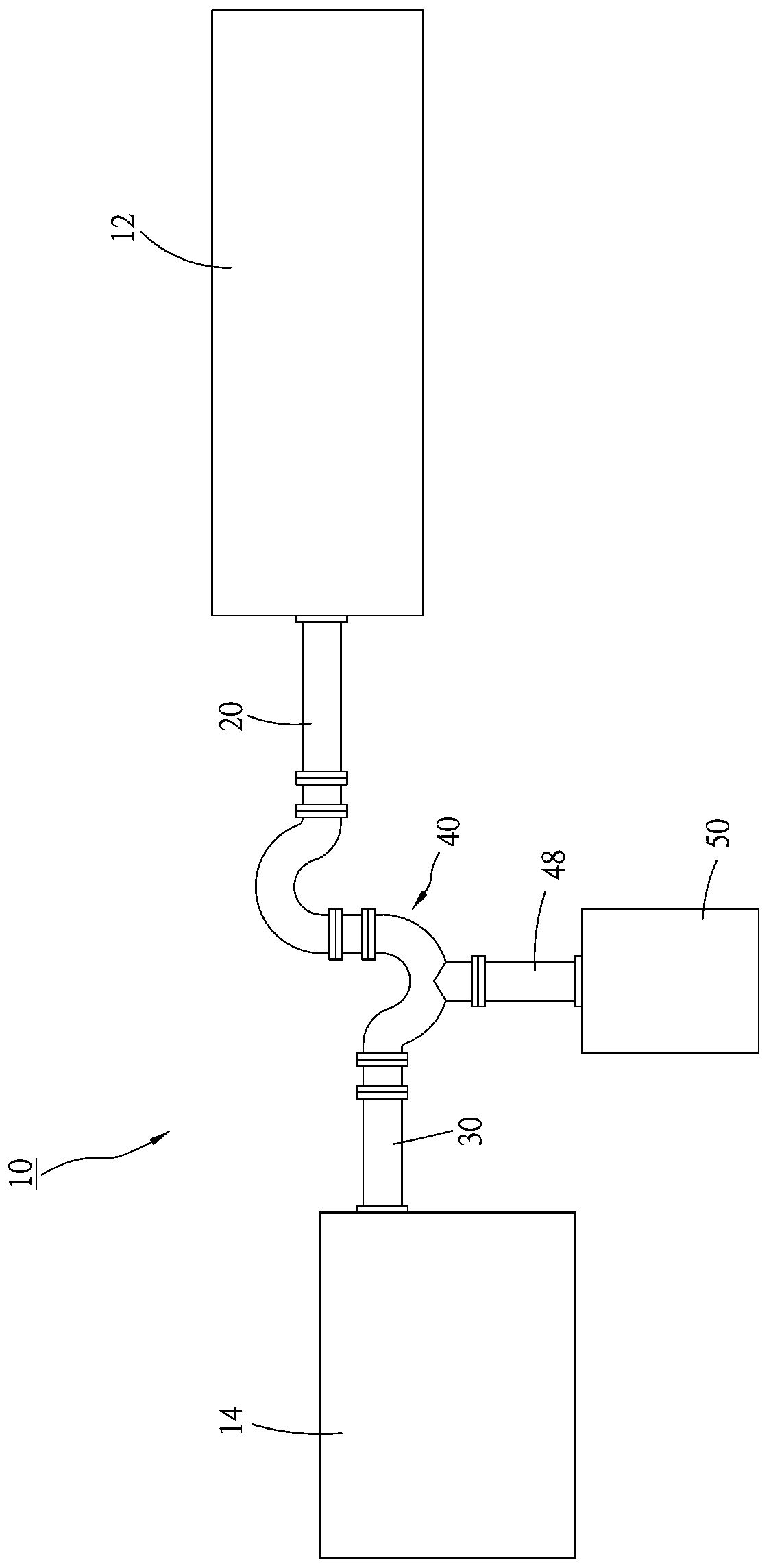
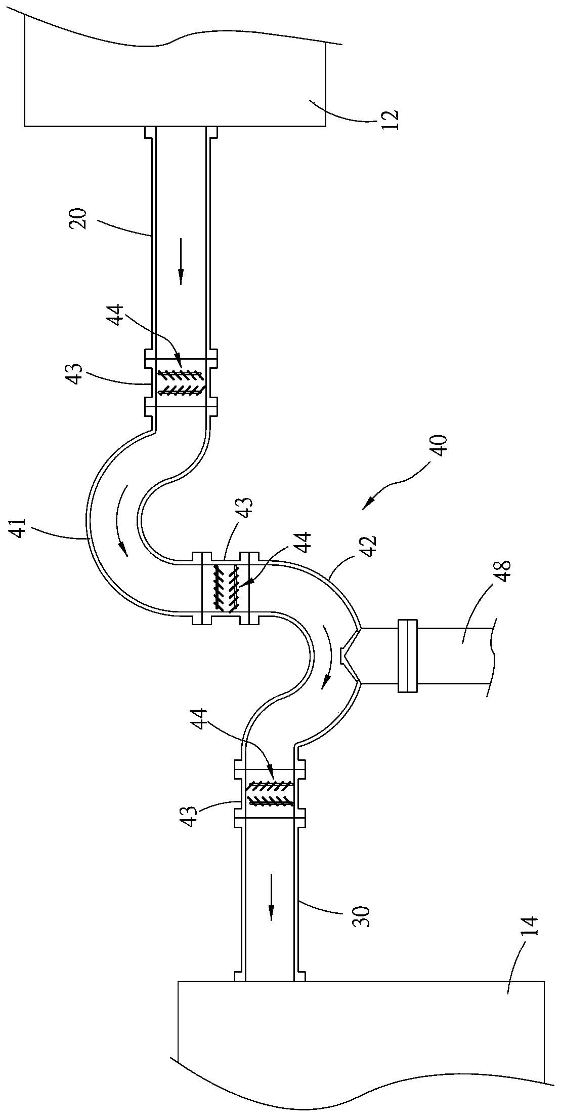
[0011] see figure 1 and 2 The condensing device 10 of the present invention is installed between a chamber 12 and a vacuum pump 14 of the vacuum coating equipment, and includes an inlet pipe 20 connecting the chamber 12, an outlet pipe 30 connecting the vacuum pump 14, and a gas outlet pipe 20 located at the inlet pipe 20. and the cold trap assembly 40 between the air outlet pipe 30.

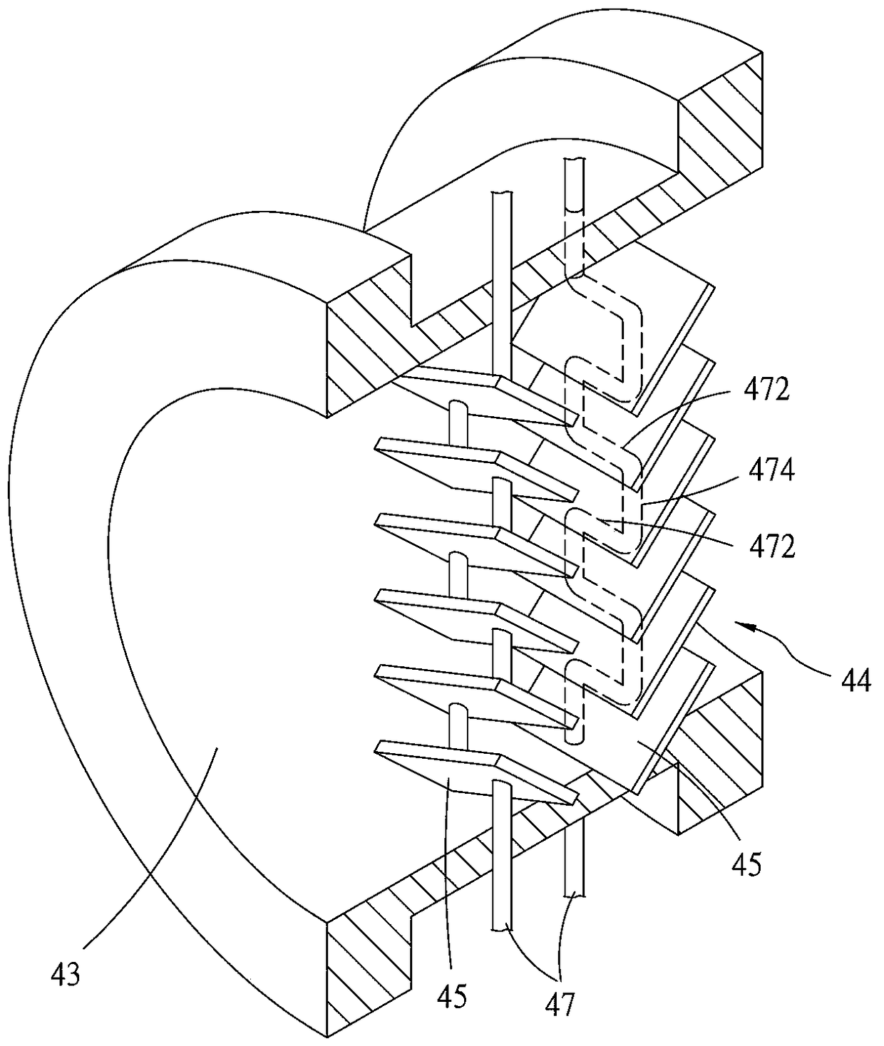
[0012] The cold trap assembly 40 has a first curved pipe 41 and a second curved pipe 42 . Between the first curved pipe 41 and the inlet pipe 20, between the first and second curved pipes 41, 42, and between the second curved pipe 42 and the air outlet pipe 30, there is a cold trap pipe respectively. 43 and connected two by two, and the first and second curved pipes 41, 42 have opposite bending directions, so that the first and second curved pipes 41, 42 form an S-shape after connection aisle. Furthermore, the cold trap assembly 40 has six baffle plate groups 44, and these baffle plate group...


PUM


Abstract

The invention relates to a condensing device for vacuum coating equipment. The condensing device comprises a gas inlet pipe, a gas outlet pipe and a cold trap component arranged between the gas inlet pipe and the gas outlet pipe, wherein the cold trap component comprises a first arc-shaped bend and a second arc-shaped bend, the first arc-shaped bend is connected together with the gas inlet pipe by virtue of a cold trap pipe, the first arc-shaped bend is connected together with the second arc-shaped bend by virtue of a cold trap pipe, the second arc-shaped bend is connected together with the gas outlet pipe by virtue of a cold trap pipe, each of the cold trap pipe is internally provided with a baffle set and each of baffle sets comprises a plurality of inclined baffles arranged in parallel and a cooling water pipe attached to each of inclined baffles. By virtue of the condensing device, vapor from the inside of the cavity can be smoothly condensed on the surface of each of inclined baffles when vapor passes through the cold trap component and the corrosion damage to the first and second arc-shaped bends can be avoided.

Description

technical field [0001] The invention relates to vacuum coating equipment, in particular to a condensing device for vacuum coating equipment. Background technique [0002] To put it simply, the so-called vacuum coating is to use a vacuum pump to pump out the residual gas in the cavity to keep the inside of the cavity in a vacuum state, then put an object to be plated (such as a substrate) into the cavity, and finally evaporate an The source (such as selenium) is heated to the state of vaporization and sublimation, so that the gas of the evaporation source is attached to the surface of the object to be plated to form a thin film. [0003] However, in addition to general water vapor and other high-boiling point vapors, the residual gas in the chamber may also contain some corrosive vapors. A cold trap is usually installed, and the cold trap mainly uses the low-temperature condensation effect to trap the residual gas in the cavity, so that the cavity has a good vacuum. As far ...

Claims


Application Information

Patent Timeline
Patent Type & Authority Patents(China)
IPC IPC(8): C23C14/56
Inventor 黄世壬廖科峰赵亨文赖文波任常宝陈官璧汪宇炎曾昭隆
Owner 生阳新材料科技(宁波)有限公司
Learn More