Power Amplifier Saturation Detection

A power amplifier and comparator technology, applied in the direction of power amplifiers, amplifiers, high-frequency amplifiers, etc., can solve problems such as violation of switching spectrum specifications, insufficient gain bandwidth of regulators to follow accurately, power amplifier PvT time masking, etc.

Inactive Publication Date: 2011-11-30
SKYWORKS SOLUTIONS INC
View PDF4 Cites 12 Cited by
  • Summary
  • Abstract
  • Description
  • Claims
  • Application Information

AI Technical Summary

Problems solved by technology

Insufficient regulator gain bandwidth to accurately follow the V_PC input signal, causing power amplifier PvT time masking and violation of switching spectrum specifications
[0008] While the technique described above with reference to FIG. 1 for detecting when a power amplifier control loop is in or near saturation is beneficial in a power amplifier system with a COVAC transistor arrangement, this technique cannot be used in some other situations.

Method used


Image

  • Power Amplifier Saturation Detection
  • Power Amplifier Saturation Detection
  • Power Amplifier Saturation Detection

Examples


Embodiment Construction

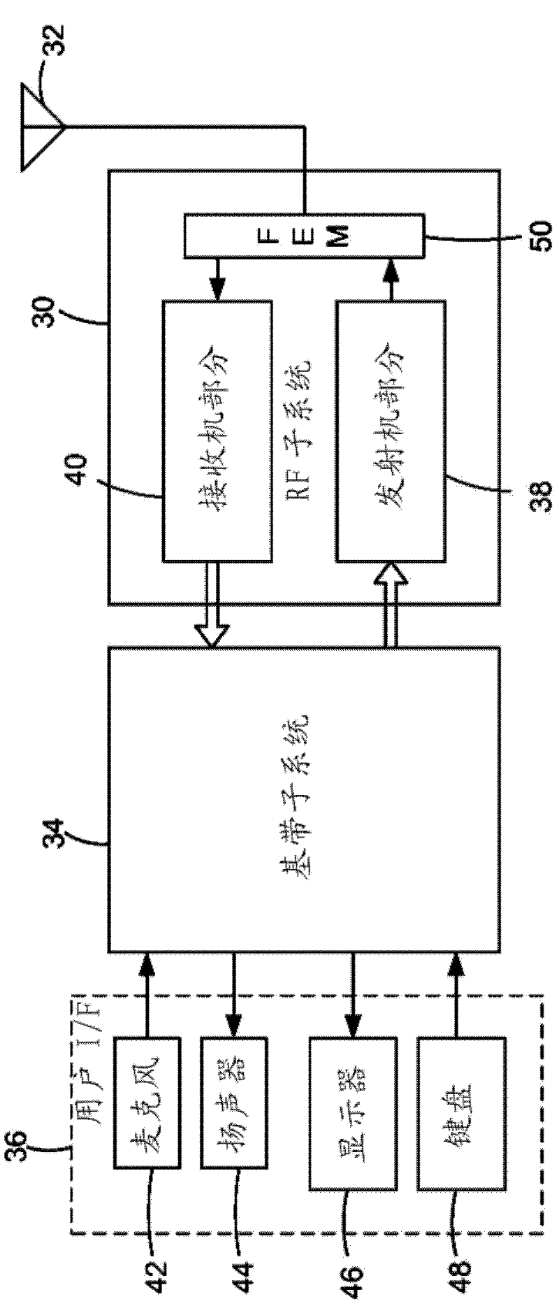
[0019] Such as figure 2 As shown in, a mobile wireless telecommunications device, such as a cellular telephone, includes a radio frequency (RF) subsystem 30, an antenna 32, a baseband subsystem 34, and a user interface portion 36, according to an exemplary embodiment of the present invention. RF subsystem 30 includes a transmitter portion 38 and a receiver portion 40 . User interface portion 36 includes microphone 42 , speaker 44 , display 46 and keyboard 48 , all of which are coupled to baseband subsystem 34 . The output of the transmitter section 38 and the input of the receiver section 40 are coupled to the antenna 32 via a front-end module (FEM) 50, which allows the transmitted RF signal generated by the transmitter section 38 and provided to the receiver The received RF signal of section 40 passes both simultaneously. However, for the transmitter portion 38, the elements listed above may be of the type conventionally included in such mobile wireless telecommunications e...


PUM


Abstract

In a portable radio transceiver, a power amplifier system includes a saturation detector that detects power amplifier saturation in response to duty cycle of the amplifier transistor collector voltage waveform. The saturation detection output signal can be used by a power control circuit to back off or reduce the amplification level of the power amplifier to avoid power amplifier control loop saturation.

Description

Background technique [0001] Radio Frequency (RF) transmitters of the type used in mobile radiotelephones (also known as cellular telephones) and other portable radio transceivers typically include transmit power control circuitry that adjusts the power of the transmitted RF signal. The power control circuit can adjust the power amplifier to increase or decrease the transmitted RF power. Adjusting the transmitted RF power is beneficial for some purposes. For example, in many types of cellular telecommunications systems, it is beneficial to transmit more RF power when the transceiver (also referred to as a handset) is farther from the nearest base station, and when the transceiver is closer to the nearest base station. In close proximity, lower transmitted RF power is beneficial. Also, in some types of multi-mode (e.g., dual-mode) transceivers, such as in transceivers capable of operating according to both the GSM (Global System for Mobile Communications) standard and the EDGE...

Claims


Application Information

Patent Timeline
Patent Type & Authority Applications(China)
IPC IPC(8): H03F3/20H04B1/40
CPCG11C7/067H04B2001/0408H03G3/007H03G3/3042H03F3/19H03F3/211H03G11/02H03F3/24H03F3/189H03F3/193H03F3/20H04B1/04H04B1/40H03F1/0216H03F2200/171H03F2200/451H03F3/195H03F3/213H03K17/06
Inventor P.R.安德里斯T.J.希M.L.杰勒德
Owner SKYWORKS SOLUTIONS INC
Why Eureka
Try Eureka