
Water jet propulsion body for ships

A mixed-flow, ship technology, applied in ship propulsion, propulsion parts, ship parts, etc., can solve the problems of simple structure, unoptimized functions, no propulsion utility, etc., to improve propulsion power and propulsion efficiency, propulsion power and propulsion efficiency. The effect of improving and reducing wave-making resistance

Inactive Publication Date: 2011-12-07
孙志伟
View PDF7 Cites 6 Cited by
  • Summary
  • Abstract
  • Description
  • Claims
  • Application Information

AI Technical Summary

Problems solved by technology

The structure of this kind of mixer is too simple, and the function is not optimized, so not only has almost no propulsion effect, but also the negative pressure difference generated worsens the stern flow field of the ship and the inflow flow field of the ducted propeller to a certain extent.
[0007] The prior art does not disclose the technical solution for structure optimization and function optimization of the external-mounted water-jet mixed-flow propulsion system, and does not solve the problem of further improving the propulsion power and propulsion efficiency of the external-mounted water-jet mixed-flow propulsion system

Method used


Image

  • Water jet propulsion body for ships
  • Water jet propulsion body for ships
  • Water jet propulsion body for ships

Examples


Embodiment 1

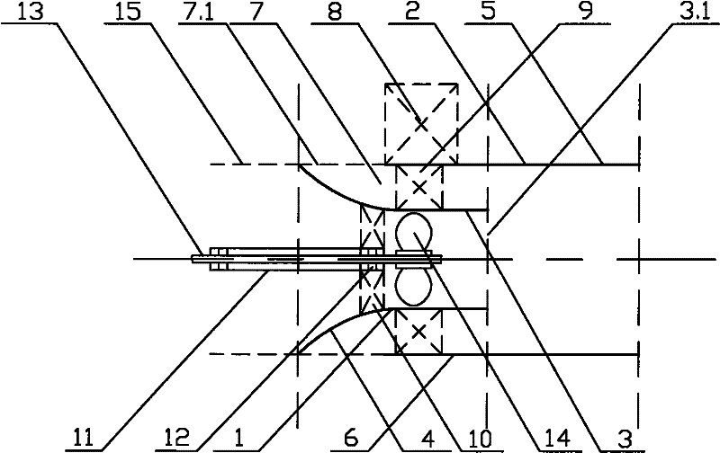
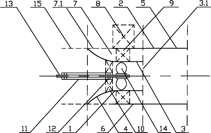
[0030] Such as figure 1 As shown, the water-jet mixed-flow propulsion body of the ship is mainly composed of a conduit 1 and a casing 2, and the conduit 1 extends into the casing 2 to form a flow mixer. The outlet portion of the conduit 1 is a jet tube 3 , the inlet portion of the conduit 1 is a bell mouth 4 , and the outer edge of the bell mouth 4 is in contact with the outer surface of the casing 2 . The sleeve pipe 2 is divided into two parts by the water spray port 3.1 of the jet pipe 3 , the outlet part is the mixed flow pipe 5 , and the inlet part is the follower pipe 6 . The outer wall surface of the conduit 1 and the tracer pipe 6 together form the tracer passage 7, and between the outer edge of the bell mouth 4 and the front end of the tracer pipe 6 is the water inlet of the tracer passage 7 and its grille 7.1. The outer wall surface of sleeve pipe 2 has body support 8, is connected and fixed with hull. There is a pipe bracket 9 between the sleeve pipe 2 and the cat...

Embodiment 2

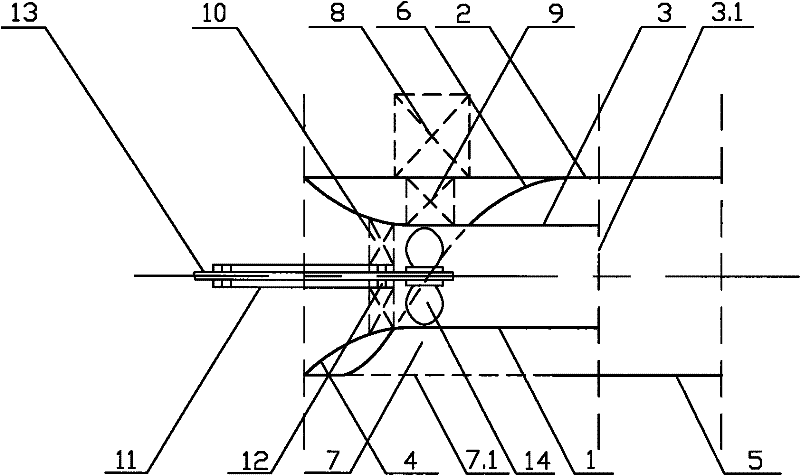
[0034] Such as figure 2 As shown, the water-jet mixed-flow propulsion body of the ship is mainly composed of a conduit 1 and a casing 2, and the conduit 1 extends into the casing 2 to form a flow mixer. The outlet part of the conduit 1 is a jet tube 3 , and the inlet part of the conduit is a bell mouth 4 . The outer edge of the bell mouth 4 is in contact with the outer wall of the casing 2, and the water inlet of the follower channel 7 and its grille 7.1 are arranged on the outer wall of the casing 2. The casing 2 is divided into two parts by the water spray port 3.1 of the jet pipe 3, and its outlet part is a mixed flow pipe 5, which communicates with the accompanying flow channel 7. The follower channel 7 is formed solely by the follower pipe 6 which has an elbow 6.1 through which the conduit 1 passes. The outer wall surface of sleeve pipe 2 has body support 8, is connected and fixed with hull. There is a pipe bracket 9 between the sleeve pipe 2 and the catheter 1 for co...


PUM


Abstract

The invention discloses a water-jet mixed-flow propulsion body of a ship, which is used to further optimize the structure and function of an external-mounted water-jet mixed-flow propulsion system, and further improve the propulsion power and propulsion efficiency. It mainly consists of a conduit and a sleeve. The conduit extends into the casing to form a flow mixer. The outlet part of the conduit is a jet tube, and the inlet part of the conduit is a bell mouth. The outer edge of the bell mouth is in contact with the outer surface of the casing. It is divided into two parts for the boundary, the outlet part of the casing is a mixed flow pipe, and the mixed flow pipe is connected with the follower channel, and the water inlet of the follower channel is on the outer surface of the casing. The bell mouth of the duct can not only reduce the hydraulic loss of the water-jet propulsion part, but also can separate and improve the inflow field of the water-jet propulsion part and the mixed-flow propulsion part, thereby reducing the wave-making resistance and improving the propulsion efficiency. The bend of the waker channel can promote the conversion of the negative pressure difference generated by the jet effect into propulsion, so the mixed flow propulsion part can recover a part of the injection power and convert it into propulsion power.

Description

technical field [0001] The invention belongs to the technical field of ship propulsion, and specifically relates to a water spray energy used for further recovering the water jet propulsion system of the ship, which is used to further improve the flow field of the ship and the water jet propulsion system of the ship. A water-jet mixed-flow propelling body for further improving the propulsion power and propulsion efficiency of the ship. Background technique [0002] The ship diversion propulsion system can be divided into three types: one is the bow and stern diversion propulsion system, including the bow and stern diversion tube and propulsion pump, etc.; the other is the midship and stern diversion propulsion system, or the built-in water jet propulsion system system; the other is the stern diversion propulsion system, which is an external water jet propulsion system, such as a water jet propulsion combination, a pump jet propeller and a ducted propeller. [0003] Compared...

Claims


Application Information

Patent Timeline
Patent Type & Authority Applications(China)
IPC IPC(8): B63H11/02
Inventor 孙志伟
Owner 孙志伟
Learn More