Method and device for controlling an internal combustion engine

A technology for internal combustion engines and equipment, applied to mechanical equipment, internal combustion piston engines, electrical control, etc., can solve the problems of wasting gas potential energy, etc., and achieve the effects of low emissions, short and simple methods

Inactive Publication Date: 2011-12-07
ROBERT BOSCH GMBH
View PDF3 Cites 4 Cited by
  • Summary
  • Abstract
  • Description
  • Claims
  • Application Information

AI Technical Summary

Problems solved by technology

As a result, a large part of th

Method used


Image

  • Method and device for controlling an internal combustion engine
  • Method and device for controlling an internal combustion engine
  • Method and device for controlling an internal combustion engine

Examples


Embodiment Construction

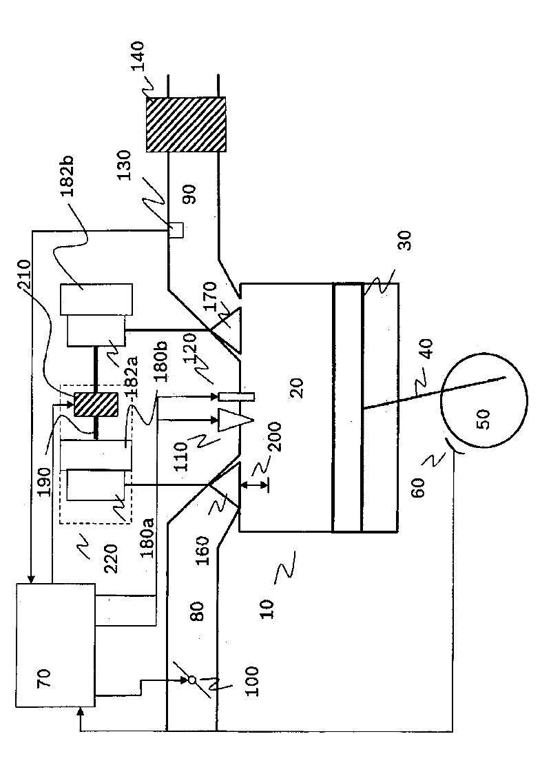
[0019] figure 1 A cylinder 10 of an internal combustion engine is shown with a combustion chamber 20 and a piston 30 connected to a crankshaft 50 by means of a connecting rod 40 . Crankshaft angle sensor 60 senses the angular position of rotating crankshaft 50 . Information about the angular position of crankshaft 50 is relayed to controller 70 .

[0020] During the downward movement of the piston 30 , air to be combusted is drawn into the combustion chamber 20 via an intake duct 80 in a known manner. As the piston 30 moves upward, the combusted air is forced out of the combustion chamber 20 through the exhaust pipe 90 . The amount of air inhaled through the intake pipe 80 is adjusted through the air charge changing device, which is a throttle valve 100 in this embodiment, and the position of the throttle valve is determined by the controller 70 .

[0021] Fuel is injected into the air sucked in from the intake pipe 80 via the injection valve 110 provided directly in the co...


PUM


Abstract

The method involves changing a switching phase of a stroke (200) and an inlet valve (160) i.e. butterfly valve, of a valve stroke changing device (220) with lean-burn phase when air-fuel ratio exhibits a value larger than one and a firing angle exceeds a maximum firing angle. A filling change device (100) is controlled such that filling at beginning of the switching phase and filling at end of the switching phase are equal. The filling change device changes size of the filling according to valve position. Independent claims are also included for the following: (1) an electrical memory medium comprising a computer program for controlling torque curve of a lean executable internal combustion engine (2) a control and/or regulating device for controlling torque curve of a lean executable internal combustion engine.

Description

technical field [0001] The invention relates to a method of the type according to the independent claims. Furthermore, objects of the invention are a computer program, an electrical storage medium and a control and regulating device. Background technique [0002] Internal combustion engines incorporating engine controls to provide multiple types of operation and multiple injections per working cycle are generally known. Also known are switching techniques for reducing the consumption of the intake valve stroke of internal combustion engines. As a result, gas-saving losses and consumption can be significantly reduced, especially in comparable gasoline engines. In particular, the switching of the intake valve strokes can be carried out with cylinder-selective actuators. [0003] Particularly cost-effective are systems for switching the strokes of the intake valves which comprise only one actuator for switching all the strokes of the intake valves. In these systems, the swi...

Claims


Application Information

Patent Timeline
IPC IPC(8): F02D43/00
CPCF02D2041/002F02D37/02Y02T10/18F02P5/045F02D2041/0012F02D41/405F02D2041/001F02D13/0226F02D41/0002F02D13/0207Y02T10/46F02P5/1504Y02T10/42Y02T10/12Y02T10/40
Inventor G.波坦H-E.贝耶M.艾勒J-M.蒙A.贝斯曼恩M.拉奎特
Owner ROBERT BOSCH GMBH
Why Eureka
Try Eureka