Use current integration to control the current flowing through the valve's coil drive

A coil drive, current integration technology, applied in electrical control, engine control, fuel injection control and other directions, can solve problems such as large deviation of injected fuel amount

Inactive Publication Date: 2011-12-07
CONTINENTAL AUTOMOTIVE GMBH
View PDF4 Cites 13 Cited by
  • Summary
  • Abstract
  • Description
  • Claims
  • Application Information

AI Technical Summary

Problems solved by technology

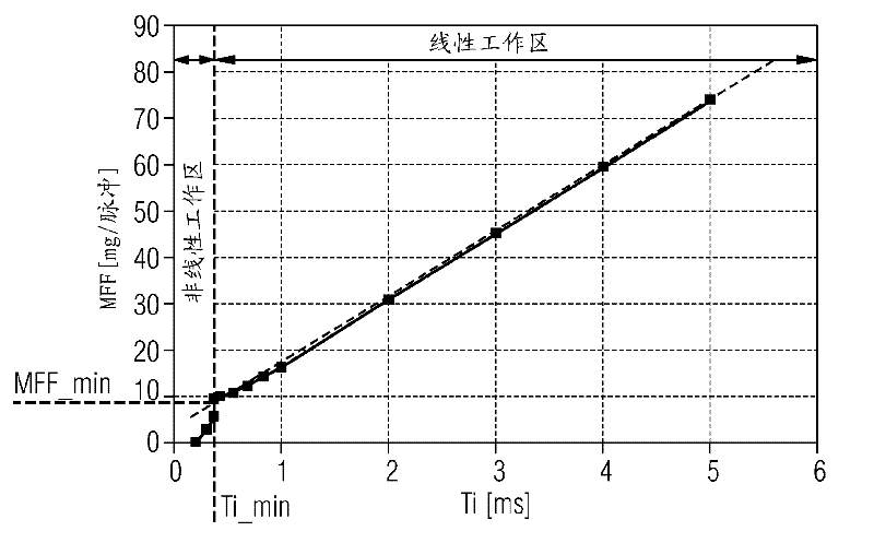
Undesired changes in the current spectrum lead to large deviations of the injected fuel quantity from the nominal value, especially in the case of small fuel quantities

Method used

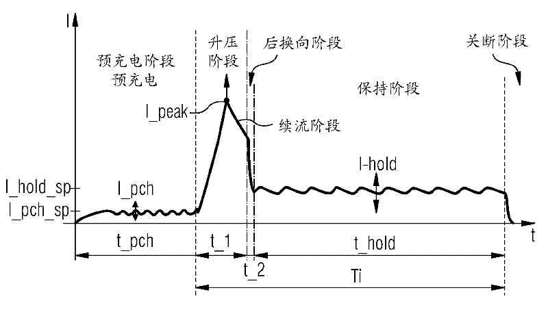

Image

  • Use current integration to control the current flowing through the valve's coil drive
  • Use current integration to control the current flowing through the valve's coil drive
  • Use current integration to control the current flowing through the valve's coil drive

Examples


Embodiment Construction

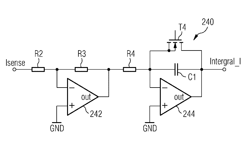
[0060] figure 1 An apparatus 100 for regulating current flow through a coil drive 110 of a direct injection valve is shown. The direct injection valve is not shown for reasons of clarity.

[0061] The regulating device 100 may be coupled to two voltage sources, wherein a first voltage source provides a first supply voltage Vbat and a second voltage source provides a second supply voltage Vboost. According to the exemplary embodiment shown here, the first supply voltage Vbat corresponds to the on-board voltage or the battery voltage of the motor vehicle. The second supply voltage Vboost is an amplified or boosted voltage, which is generated from the first supply voltage Vbat, for example by means of conventional DC-DC conversion.

[0062] The line segment driver 110 can be coupled to the first supply voltage Vbat via a first switching element T1 embodied as a transistor and to the second supply voltage Vboost via a second switching element T2 also embodied as a transistor. A...


PUM


Abstract

A device and a method are provided which allow direct injection valves with coil actuation (110) in particular to reduce the pulse-to-pulse variation of the fuel quantity injected through the direct injection valves in a manner also based on Regulation of the current integral of the coil drive (110), especially during the boost phase of the current excitation spectrum of the coil drive (100). Furthermore, a computer program for carrying out the method is described.

Description

technical field [0001] The invention relates to a coil drive for actuating a valve, in particular a fuel direct injection valve for an electric motor of a motor vehicle. Background technique [0002] In order to operate modern internal combustion engines and to comply with strict emission limit values, the electric motor control determines the air mass enclosed in the cylinders per operating cycle by means of a so-called cylinder filling model. Depending on the modeled air mass and the desired ratio (λ) between the air quantity and the fuel quantity, the corresponding setpoint fuel quantity (MFF_SP) is injected via the injection valve. This achieves that the fuel quantity to be injected is determined such that there is an incremental optimum for exhaust gas aftertreatment in the catalyst. For four-stroke electrodes with direct injection with internal mixing, the fuel is injected directly into the combustion chamber at a pressure of 40 to 200 bar. [0003] In addition to th...

Claims


Application Information

Patent Timeline
Patent Type & Authority Applications(China)
IPC IPC(8): F02D41/20
CPCF02D2041/2058F02D2041/2003F02D41/20F02D45/00
Inventor J.比尔S.博兹
Owner CONTINENTAL AUTOMOTIVE GMBH
Why Eureka
Try Eureka