

Frameless solar panel and manufacturing method thereof
A technology of solar cell panels and manufacturing methods, applied to circuits, photovoltaic power generation, electrical components, etc., capable of solving problems such as performance degradation of solar cell panels, short circuit of solar cell components, etc.
- Summary
- Abstract
- Description
- Claims
- Application Information
AI Technical Summary
Problems solved by technology
Method used
Image

Examples
no. 1 approach
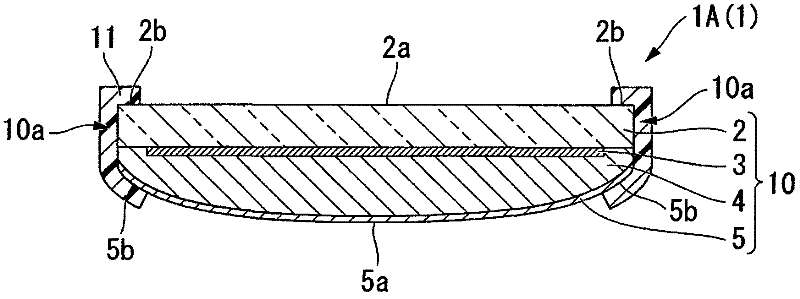
[0046] figure 1 It is a schematic cross-sectional view showing the first embodiment of the frameless solar cell panel according to the present invention.
[0047]A frameless solar cell panel 1A ( 1 ) of the first embodiment includes a laminate 10 and a silicon-based sealing material 11 . In the laminated body 10, the transparent first base material 2, the power generation part 3, the sealing layer 4, and the back sheet 5 are laminated|stacked in this order. In addition, a silicon-based sealing material 11 is disposed on the side surface 10 a (end portion) of the laminated body 10 .
[0048] In the frameless solar cell panel 1A(1) of the first embodiment, by arranging the silicon-based sealing material 11 on the side surface 10a of the above-mentioned laminate 10, the weather resistance to ultraviolet rays (UV) or moisture is ensured, and the Sufficient rigidity for protecting the laminated body 10 . Accordingly, in the first embodiment, a solar cell panel having a frameles...
no. 2 approach
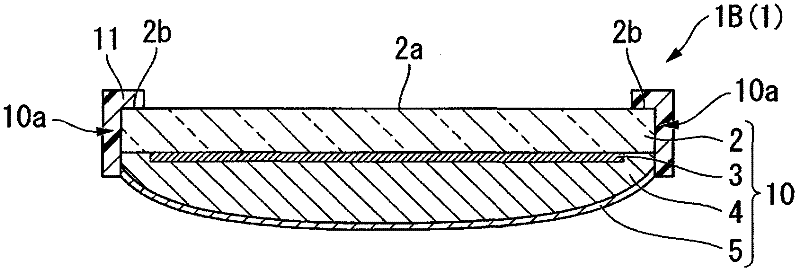
[0069] exist image 3 In , the same symbols are assigned to the same components as those in the first embodiment, and descriptions thereof are omitted or simplified.
[0070] exist image 3 In the shown frameless solar cell panel 1B ( 1 ), the silicon-based sealing material 11 covers at least the side surface 10 a of the laminate 10 and the outer edge 2 b on the outer surface 2 a of the first substrate 2 . The silicon-based sealing material 11 has a substantially L-shape in the cross section of the laminated body 10 .
[0071] Also in this configuration, the same effect as that of the first embodiment can be obtained.
no. 3 approach
[0073] exist Figure 4 In , the same symbols are assigned to the same components as those in the first embodiment, and descriptions thereof are omitted or simplified.
[0074] exist Figure 4 In the illustrated frameless solar cell panel 1C ( 1 ), an adhesive layer 12 made of butyl rubber is disposed between the silicon-based sealing material 11 and the laminate 10 . Butyl rubber has excellent resistance to water vapor transmission. Since the adhesive layer 12 is disposed, it is possible to more reliably prevent moisture and the like from entering the laminate 10 from the side face 10 a of the laminate 10 . Accordingly, the frameless solar cell panel 1C(1) having further excellent moisture resistance can be realized.
[0075] (Manufacturing method)
[0076] Next, a method of manufacturing the above-mentioned frameless solar cell panel will be described.
[0077] In the method of manufacturing a frameless solar cell panel, a laminate 10 in which a transparent first base ma...
PUM
 Abstract
Description
Claims
Application Information