Washing machine bionic hand rub frequency conversion deceleration clutch

A deceleration clutch and bionic hand technology, which is applied in other washing machines, washing devices, textiles and papermaking, etc., can solve the problems of complicated installation and connection, not much improvement in motor efficiency, and many connecting parts of the main part, so as to achieve flexible and smooth operation , good insulation and easy installation

Active Publication Date: 2011-12-14
宁波普尔机电制造有限公司
View PDF7 Cites 20 Cited by
  • Summary
  • Abstract
  • Description
  • Claims
  • Application Information

AI Technical Summary

Problems solved by technology

However, the patented technical solution is simply to install the single-phase asynchronous motor installed next to the deceleration clutch of the washing machine directly and vertically below the clutch; since the efficiency of the motor has not been greatly improved, the washing method is single, the function is simple, and its installation and connection are complicated. , high precision requirements, not suitable for mass production, and the washing machine cannot realize frequency conversion rubbing washing, frequency conversion multi-speed dehydration
Another example is that the patent No. ZL00234747.4 discloses a washing machine deceleration clutch directly driven by a brushless motor. Complicated, only ordinary washing methods can be realized, there are many connecting parts of the main parts, and the installation accuracy of the clutch is too high, and it has the disadvantage of high failure rate, so this patented technical solution is not suitable for mass production products

Method used


Image

  • Washing machine bionic hand rub frequency conversion deceleration clutch
  • Washing machine bionic hand rub frequency conversion deceleration clutch
  • Washing machine bionic hand rub frequency conversion deceleration clutch

Examples


Embodiment Construction

[0017] Embodiments of the present invention will be described in further detail below in conjunction with the accompanying drawings.

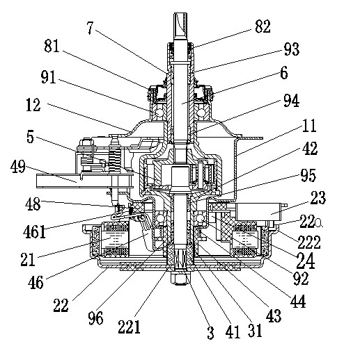
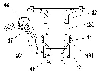
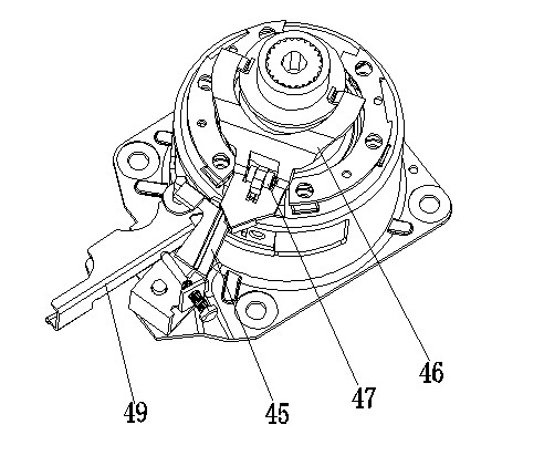
[0018] Figure 1 to Figure 4 Shown is the structural representation of the present invention.

[0019] The reference signs are: lower housing 11, upper housing 12, plastic-encapsulated brushless DC motor stator 21, outer rotor 22 of DC brushless motor, upper end edge 22a, via hole boss 221, round shoulder 222, Hall Component feedback assembly 23, stator fastening screw 24, input shaft 3, lower end boss side 31, bushing 41, clutch shaft 42, outer peripheral bearing boss 421, clutch slider 43, ring boss 431, clutch spring 44, Clutch lever 45, clutch pressure plate 46, tension spring 461, rotating mandrel 47, rotating shaft fixed block 48, push rod 49, gear reduction system 5, pulsator shaft 6, dehydration shaft 7, large sealing ring 81, small sealing ring 82, The first support bearing 91 , the second support bearing 92 , the first oil bearing 9...


PUM


Abstract

The invention discloses a variable-frequency speed-reducing clutch of bionic hand rubbing of a washing machine. The clutch provided by the invention comprises a lower shell and an input shaft which are matched; the lower shell is equipped with a stator of a direct-current brushless motor and the end part of the input shaft is connected with an external rotor of the direct-current brushless motor;the stator of the direct-current brushless motor is located at an inner cavity of the external rotor of the direct-current brushless motor and the input shaft is assembled with a sliding clutch mechanism composed of a shaft sleeve, a clutch shaft, a clutch sliding block and a clutch spring; the shaft sleeve covers the input shaft and the clutch shaft is located above the shaft sleeve to rotatablycover the input shaft; the shaft sleeve and the clutch shaft are all provided with peripheral splines; guiding splines on the inner periphery of the clutch sliding block are slidingly matched with the peripheral spline of the clutch shaft; the clutch spring is pressed on an annular lug boss on the periphery of the clutch sliding block and the clutch sliding block is connected with a clutch control mechanism. The clutch provided by the invention realizes the variable-frequency washing of the bionic hand rubbing of the washing machine; and the clutch enriches the washing function and has the advantages of low noise, energy source conversation, good safety performance and the like.

Description

technical field [0001] The invention relates to the technical field of a fully automatic pulsator washing machine, in particular to a deceleration clutch of a washing machine, in particular to a bionic hand rubbing frequency conversion deceleration clutch of a washing machine. Background technique [0002] Existing technology is installed side by side with washing machine deceleration clutch and single-phase asynchronous motor as the washing machine newly released on the market, by belt pulley and belt transmission. The deceleration clutch of this type of washing machine has low efficiency, high noise, and poor practicability; therefore, relevant technical personnel have proposed a technical scheme in which the motor and the clutch are vertical and coaxially installed. For example, the Chinese utility model patent No. ZL00260194.x discloses a fully automatic washing machine with cup-shaped rotor single-bearing motor and its special clutch device. transmission efficiency. H...

Claims


Application Information

Patent Timeline
Patent Type & Authority Applications(China)
IPC IPC(8): D06F37/40
Inventor 林其平
Owner 宁波普尔机电制造有限公司
Why Eureka
Try Eureka