Integrated pressure reducing valve

A pressure reducing valve, an integrated technology, applied in the field of fluid pressure reducing valves, can solve the problems of inconvenient maintenance of pressure reducing valves, poor control accuracy, difficult disassembly, etc., and achieve the effect of convenient maintenance, reliable moving performance, and improved reliability

Inactive Publication Date: 2011-12-14
陈建华
View PDF8 Cites 10 Cited by
  • Summary
  • Abstract
  • Description
  • Claims
  • Application Information

AI Technical Summary

Problems solved by technology

[0002] The pressure reducing valve is a special device that automatically reduces the working pressure of the pipeline. It can reduce the high water pressure in the pipeline before the valve to the level required by the pipeline behind the valve. The pressure reducing valve is widely used in high-rise buildings and urban water supply Areas, mines and other occasions where the water pressure of the pipe network is too high to ensure that each water point in the water supply system obtains appropriate service water pressure and flow; the existing pressure reducing valve, such as the Chinese patent application number published on May 23, 2007, is A "water pressure reducing valve" of 200510061618.X, which is equipped with a water inlet, a water outlet, a valve stem, a spring, a spring seat, a pressure regulating cover, a pressure regulating screw and a filter screen, etc., which can realize the low pressure of the water outlet It is based on the pressure of the water inlet and can adjust the pressure of the water outlet. However, the filter is located at the water inlet, between the pressure regulating cover and the water flow control port. It is difficult to disassemble and clean. There is no valve at the water inlet. The valve will cause inconvenience, in addition, the structure of the valve stem is relatively simple, and there is no pressure monitoring channel at the water outlet, so the control accuracy is poor

Method used


Image

  • Integrated pressure reducing valve
  • Integrated pressure reducing valve
  • Integrated pressure reducing valve

Examples


Embodiment Construction

[0016] The present invention will be described in further detail below in conjunction with the accompanying drawings and specific embodiments.

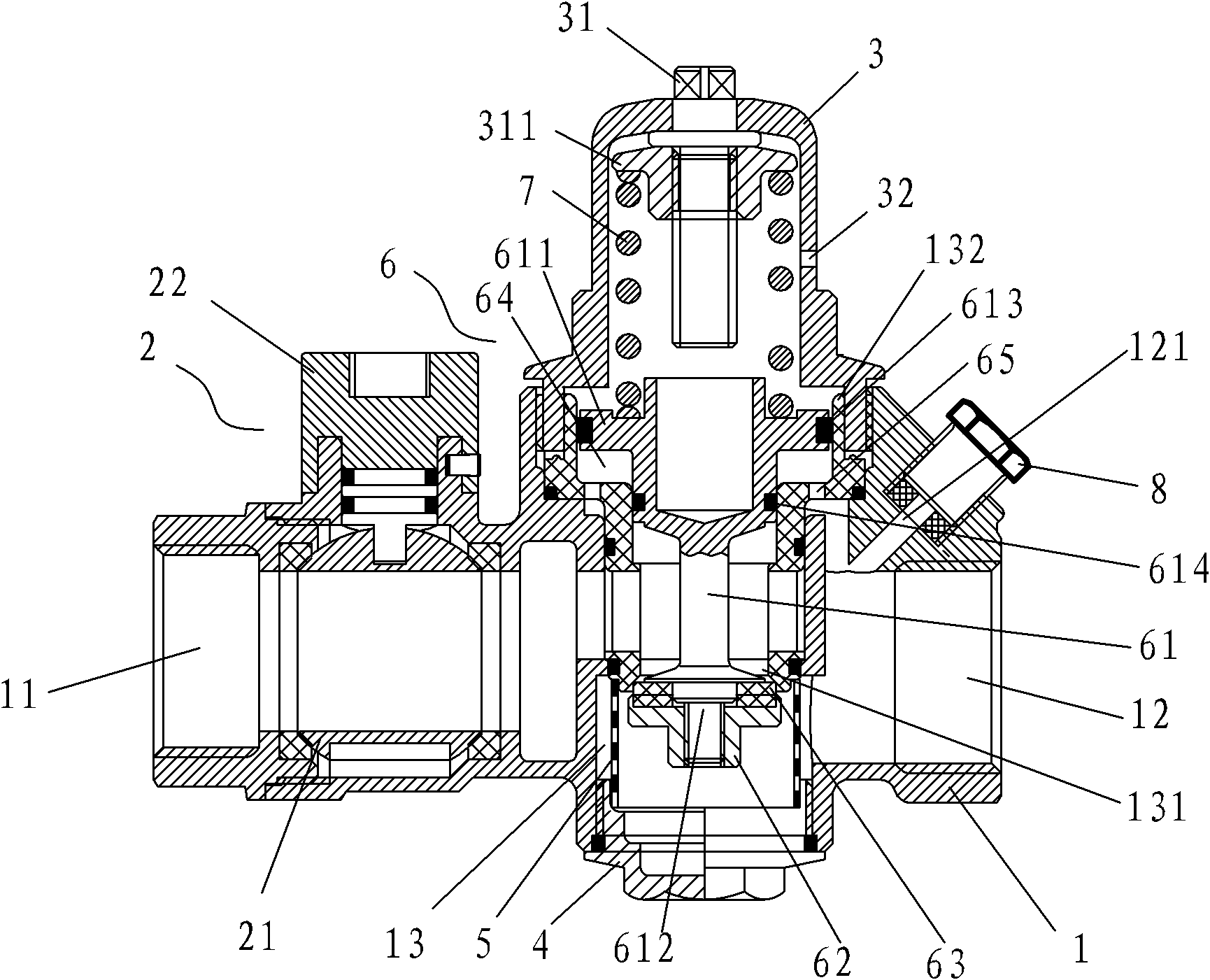
[0017] figure 1 As shown, an integrated pressure reducing valve includes a valve body 1. The valve body 1 is provided with a horizontal water inlet channel 11 and a water outlet channel 12. The water inlet channel 11 is provided with a ball valve 2. The valve body 1 is also provided with a vertical To the water flow control channel 13, there is a water flow control port 131 in the middle of the water flow control channel 13 to communicate with the water inlet channel 11 and the water outlet channel 12. The upper part of the vertical water flow control channel 13 is equipped with the upper valve cover 3, and the lower part is equipped with the lower valve cover 4, and the water flow A filter 5 is provided between the control port 131 and the water outlet channel 12, and the filter 5 is located at the upper end of the lower valve cover ...


PUM


Abstract

The invention discloses an integrated pressure reducing valve, comprising a valve body, the valve body is provided with a horizontal water inlet passage and a water outlet passage, a ball valve is arranged on the water inlet passage, and a vertical valve connecting the water inlet passage and the water outlet passage is arranged on the valve body. To the water flow control channel, the upper part of the water flow control channel is equipped with an upper valve cover, and the lower part is equipped with a lower valve cover. The upper part of the stem is a piston structure, the lower part of the valve stem is equipped with a valve disc and a valve disc gasket, and the valve stem is installed in the water flow control channel in a movable manner up and down, and the upper part of the valve stem cooperates with the upper part of the water flow control channel to form a The control air chamber has a through hole connecting the control air chamber and the water outlet channel. The upper valve cover is equipped with an adjusting screw and a spring seat. A spring is provided between the spring seat and the upper end of the valve stem. There is a through hole connected to the atmosphere on the upper valve cover. The invention has high reliability, good maintenance performance, and high pressure control precision of the water outlet channel.

Description

technical field [0001] The invention relates to the technical field of valves, in particular to a fluid pressure reducing valve which makes the outlet pressure of the valve lower than the inlet pressure. Background technique [0002] The pressure reducing valve is a special device that automatically reduces the working pressure of the pipeline. It can reduce the high water pressure in the pipeline before the valve to the level required by the pipeline behind the valve. The pressure reducing valve is widely used in high-rise buildings and urban water supply Areas, mines and other occasions where the water pressure of the pipe network is too high to ensure that each water point in the water supply system obtains appropriate service water pressure and flow; the existing pressure reducing valve, such as the Chinese patent application number published on May 23, 2007, is A "water pressure reducing valve" of 200510061618.X, which is equipped with a water inlet, a water outlet, a v...

Claims


Application Information

Patent Timeline
Patent Type & Authority Applications(China)
IPC IPC(8): F16K13/00F16K35/16F16K27/00F16K17/30
Inventor 陈建华
Owner 陈建华
Why Eureka
Try Eureka