Combined switch control system and control method

A combination switch and control system technology, which is applied in the direction of electric switches, vehicle maintenance, electrical components, etc., can solve the problems of complex wiring harness of combination switches, which is not conducive to cost saving and reliability, high temperature of switch contact points, etc., and achieves the improvement of assembly process performance, improved reliability and usability, and extended service life

Inactive Publication Date: 2011-12-14
力帆科技(集团)股份有限公司
View PDF3 Cites 9 Cited by
  • Summary
  • Abstract
  • Description
  • Claims
  • Application Information

AI Technical Summary

Problems solved by technology

The traditional automotive combination switch is a mechanical high-current control switch, and each sub-switch inside it has contacts. The closing or opening of these contacts is used to transmit signals or drive loads. Generally, these switches need to carry a large load current, which can be Reaching 20A, in order to allow such a large load current to pass, the contact of the automobile combination switch and the mechanism of operating the contact are usually designed with a larger shape and size, and are made of precious metals such as copper or silver alloys, so this kind of Combination switches are large in size, complex in internal structure, heavy in weight, and high in cost. In addition, the large current passing through the working process can easily cause high temperature at the contact point of the switch, which will cause burning and melting of the local contact position of the switch, thereby making the switch invalid and poor in reliability.
At the same time, since the traditional steam combination switch is a combination of multiple function switches, and each function switch has multiple controls and logics, each control function corresponds to an output circuit. Therefore, the more functions of the traditional combination switch, the more output circuit. More, the more complex the wiring harness of the combination switch, which is very detrimental to saving costs and improving reliability

Method used


Image

  • Combined switch control system and control method
  • Combined switch control system and control method
  • Combined switch control system and control method

Examples


Embodiment Construction

[0029] In order to make the purpose, technical solution, and advantages of the present invention clearer, the present invention will be described in further detail below with reference to the accompanying drawings.

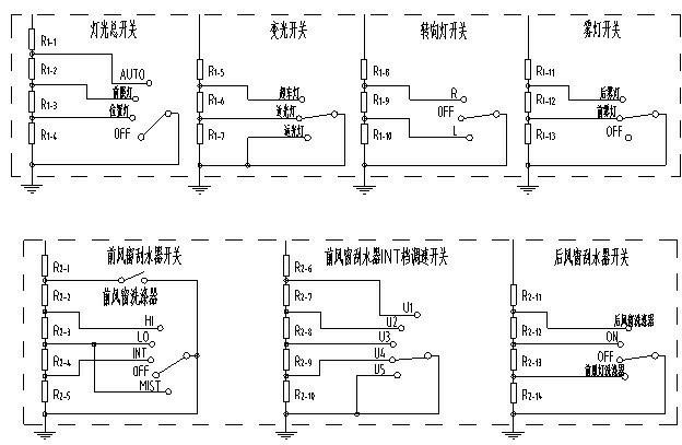
[0030] figure 1 It is a structural schematic diagram of the control system of the present invention. It can be seen from the figure that the combination switch control system includes a combination switch, BCM and controlled components. The output end of the combination switch is connected to the signal input end of the BCM, the combination switch receives the driver's control command and transmits the control command to the BCM in the form of a coded signal, the output end of the BCM is connected to the input end of the controlled component through the data bus, The BCM decodes the received encoded signal and edits it into a message and sends it to the data bus. The controlled component receives the message sent by the BCM from the data bus and performs correspon...


PUM


Abstract

The invention discloses a combined switch control system and control method. The control system comprises a combined switch, a BCM (body control module) and a controlled component; an output end of the BCM is connected with an input end of the controlled component through a data bus. A driver controls the action of the combined switch, the combined switch emits a control request signal and transmits the signal to the BCM in a coding manner; the control request signal is edited as a message after being decoded by the BCM and then sent to the data base; and the controlled component receives themessage sent by the BCM and performs the corresponding action. The control system in the invention can realize control of the lamps and the wipers in a small current, can reduce the fault rate of theswitch and improves the service life of the switch; since each switch is provided with a plurality of control functions, the output loop and wiring are reduced, the design cost is reduced, and the assembling process performance, the reliability of the system and the security of the circuit are improved. The BCM and the data bus body network are introduced into the control method provided by the invention, thus, the wiring harness is optimized and the reliability and comfortableness of an automobile are improved.

Description

technical field [0001] The invention relates to the field of automobile control, in particular to a combined switch control system and control method using small current control. [0002] Background technique [0003] The car combination switch is a multifunctional combination switch used to control lighting and light signal devices and other accessories. The traditional automotive combination switch is a mechanical high-current control switch, and each sub-switch inside it has contacts. The closing or opening of these contacts is used to transmit signals or drive loads. Generally, these switches need to carry a large load current, which can be Reaching 20A, in order to allow such a large load current to pass, the contact of the automobile combination switch and the mechanism of operating the contact are usually designed with a larger shape and size, and are made of precious metals such as copper or silver alloys, so this kind of Combination switches are large in size, com...

Claims


Application Information

Patent Timeline
Patent Type & Authority Applications(China)
IPC IPC(8): H01H9/54H01H89/00B60Q1/00B60S1/08
Inventor 陈雨康周映东唐利波
Owner 力帆科技(集团)股份有限公司
Why Eureka
Try Eureka