Microstrip Array Antenna with Low Coupling and Small Spacing

A technology of microstrip array and small spacing, applied in the direction of antenna, independent non-interaction antenna combination, antenna coupling, etc., can solve the problems of increasing antenna volume, antenna shielding effect, reducing coupling coefficient between antennas, etc., to achieve isolation High degree, easy to conform, improve the effect of coupling

Inactive Publication Date: 2011-12-14
SHANGHAI JIAO TONG UNIV
View PDF5 Cites 6 Cited by
  • Summary
  • Abstract
  • Description
  • Claims
  • Application Information

AI Technical Summary

Problems solved by technology

[0003] After searching the existing technical literature, it is found that the Chinese patent application number: CN200810064729.X, the patent publication number: CN 101316008A, the invention patent name is: MIMO mobile terminal multi-antenna with high isolation and low correlation characteristics, the main body of the antenna is double-layer Dielectric structure, the patch antenna is located on the upper surface of the upper medium, and the lower surface is the lower floor. By setting a dumbbell-shaped opening in the lower floor, the isolation between the patches ca

Method used


Image

  • Microstrip Array Antenna with Low Coupling and Small Spacing
  • Microstrip Array Antenna with Low Coupling and Small Spacing
  • Microstrip Array Antenna with Low Coupling and Small Spacing

Examples


Embodiment 1

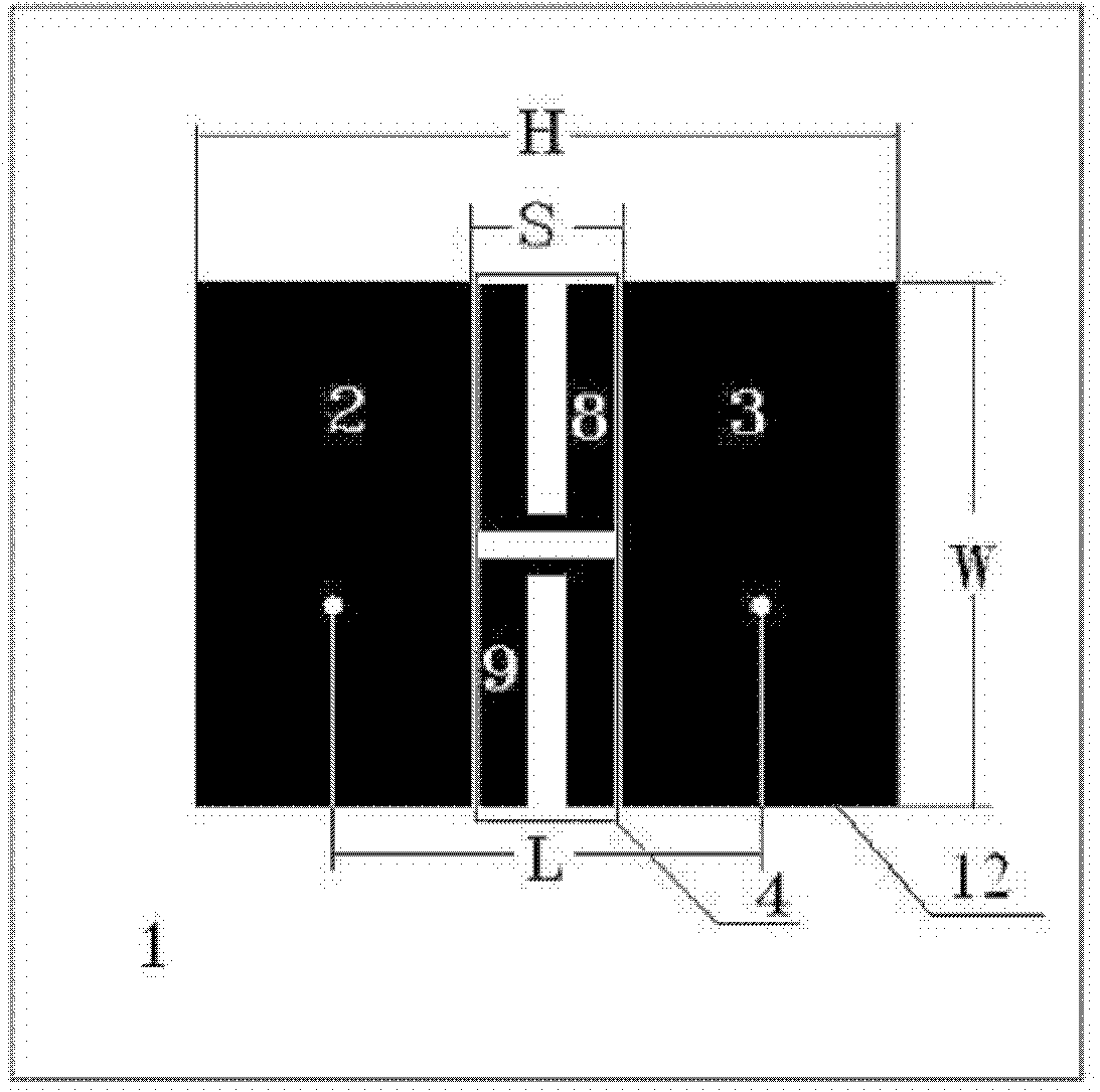
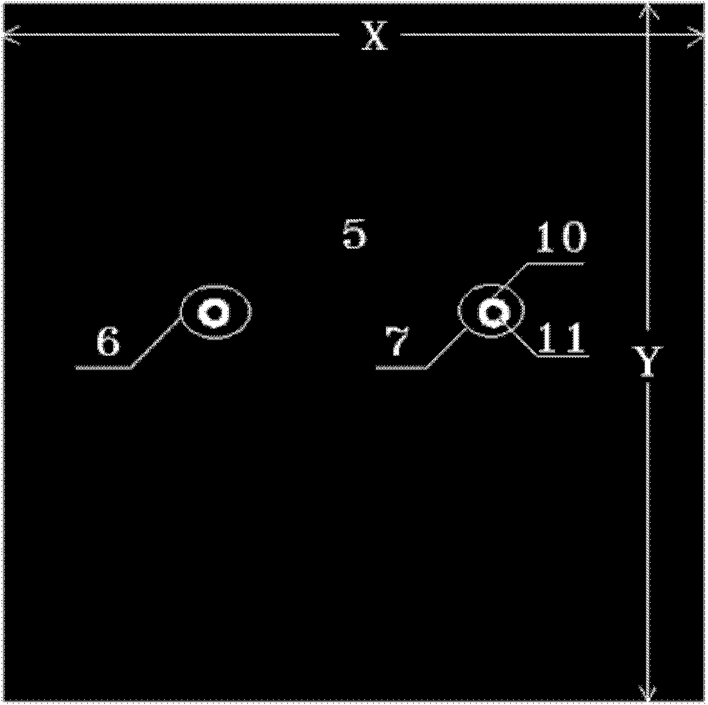
[0022] Such as figure 1 with figure 2 As shown, this embodiment includes: a dielectric board 1, a first radiation array unit 2, a second radiation array unit 3, a microstrip decoupling unit 4, a ground plate 5, a first feed element 6 and a second feed element 7 , wherein: the two radiation array units 2, 3 and the microstrip decoupling unit 4 are attached to one side of the dielectric board 1, the first radiation array unit 2 and the second radiation array unit 3 are respectively connected to the first feeding element 6 It is connected with the second feed element 7 , the two feed elements 6 , 7 are connected with the ground plate 5 , and the ground plate 5 is arranged on the other side of the dielectric plate 1 .

[0023] The first radiation array unit 2 and the second radiation array unit 3 are placed symmetrically, the radiation array units 2 and 3 are microstrip antenna units with quadrilateral patches, and the distance S between the two radiation array units 2 and 3 is ...


PUM


Abstract

A microstrip array antenna with low coupling and small spacing in the field of wireless communication technology, including: a dielectric plate, two radiation array units, a microstrip decoupling unit, a ground plate and two feeding elements, two radiation array units and a microstrip The strip decoupling units are all attached to one side of the dielectric board, the first radiating array unit and the second radiating array unit are respectively connected to the first feeding element and the second feeding element, and the two feeding elements are connected to the ground plate, The ground plate is disposed on the other side of the dielectric board. The invention uses a traditional microstrip line as a decoupling unit, which is easy to conform, has a simple structure, can better improve coupling, and has high isolation.

Description

technical field [0001] The invention relates to a device in the technical field of wireless communication, in particular to a microstrip array antenna with low coupling and small spacing. Background technique [0002] With the rapid development of communication technology, people put forward higher requirements for high-speed wireless communication. MIMO (Multiple-Input Multiple-Output, Multiple-Input Multiple-Output) technology adopts multiple antennas at the transmitting end and the receiving end, which can double the capacity of the communication system and the utilization rate of spectrum without increasing the bandwidth. Breaking through the traditional theory that the multipath signal is the limitation that the interference of the system must be suppressed, and making full use of the multipath signal is a research hotspot in the next generation of wireless communication. However, array antennas based on MIMO technology require a high degree of isolation between units,...

Claims


Application Information

Patent Timeline
IPC IPC(8): H01Q1/38H01Q1/48H01Q1/52H01Q13/08H01Q21/28
Inventor 陈念叶声金荣洪耿军平梁仙灵
Owner SHANGHAI JIAO TONG UNIV
Why Eureka
Try Eureka