Slurry regeneration device and method

A regeneration device and slurry technology, applied to fine working devices, stone processing equipment, grinding machines, etc., can solve problems such as poor accuracy, and achieve the effects of improving operability, reducing the number of parts, and reducing costs

Inactive Publication Date: 2011-12-14
IHI ROTATING MACHINERY ENG CO LTD
View PDF6 Cites 1 Cited by
  • Summary
  • Abstract
  • Description
  • Claims
  • Application Information

AI Technical Summary

Problems solved by technology

This choice is mainly made by the operator based on experience, and the accuracy is poor.

Method used


Image

  • Slurry regeneration device and method
  • Slurry regeneration device and method
  • Slurry regeneration device and method

Examples


Embodiment Construction

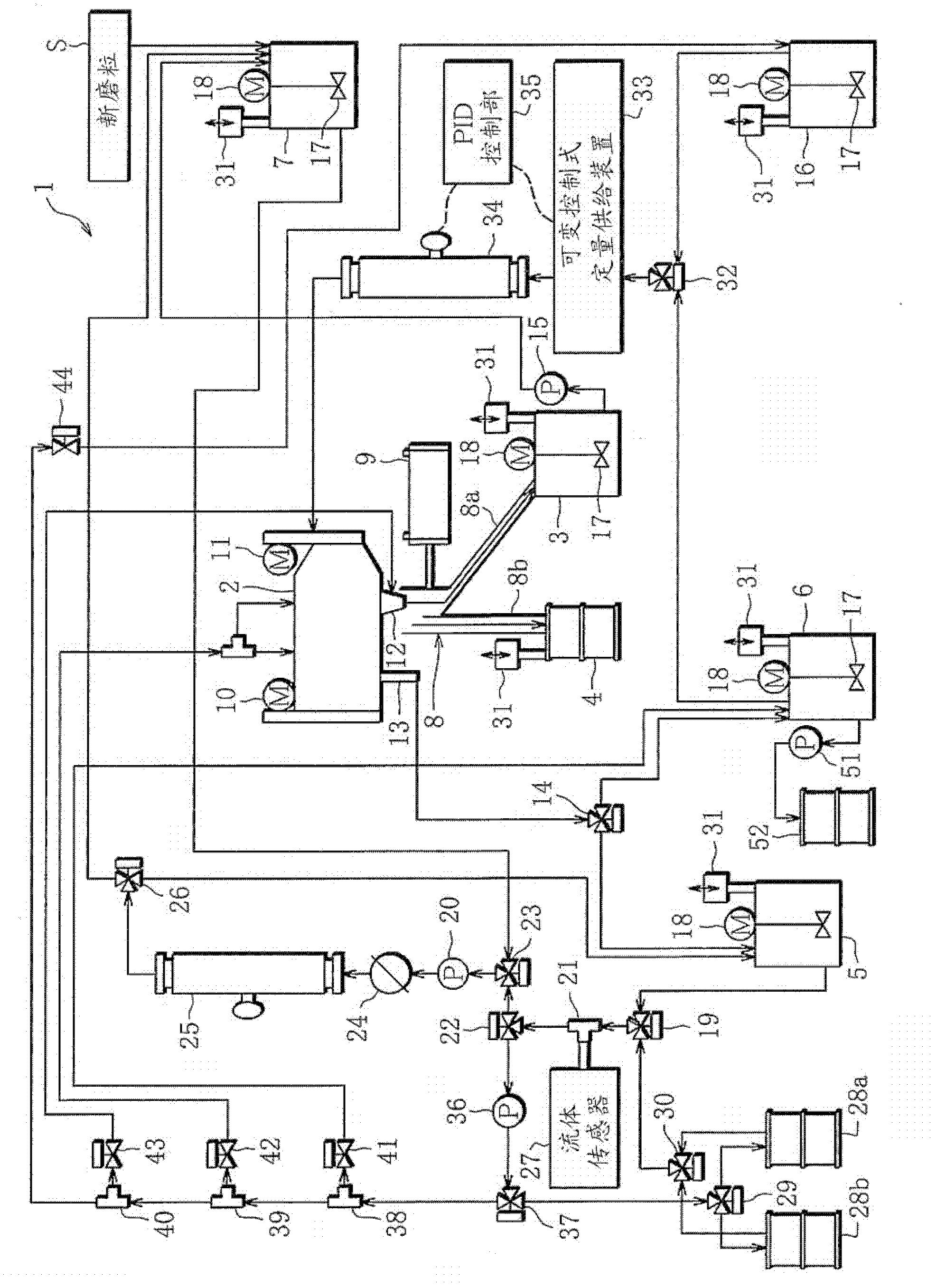
[0081] figure 1 It is a schematic diagram of the slurry regeneration apparatus of this invention.

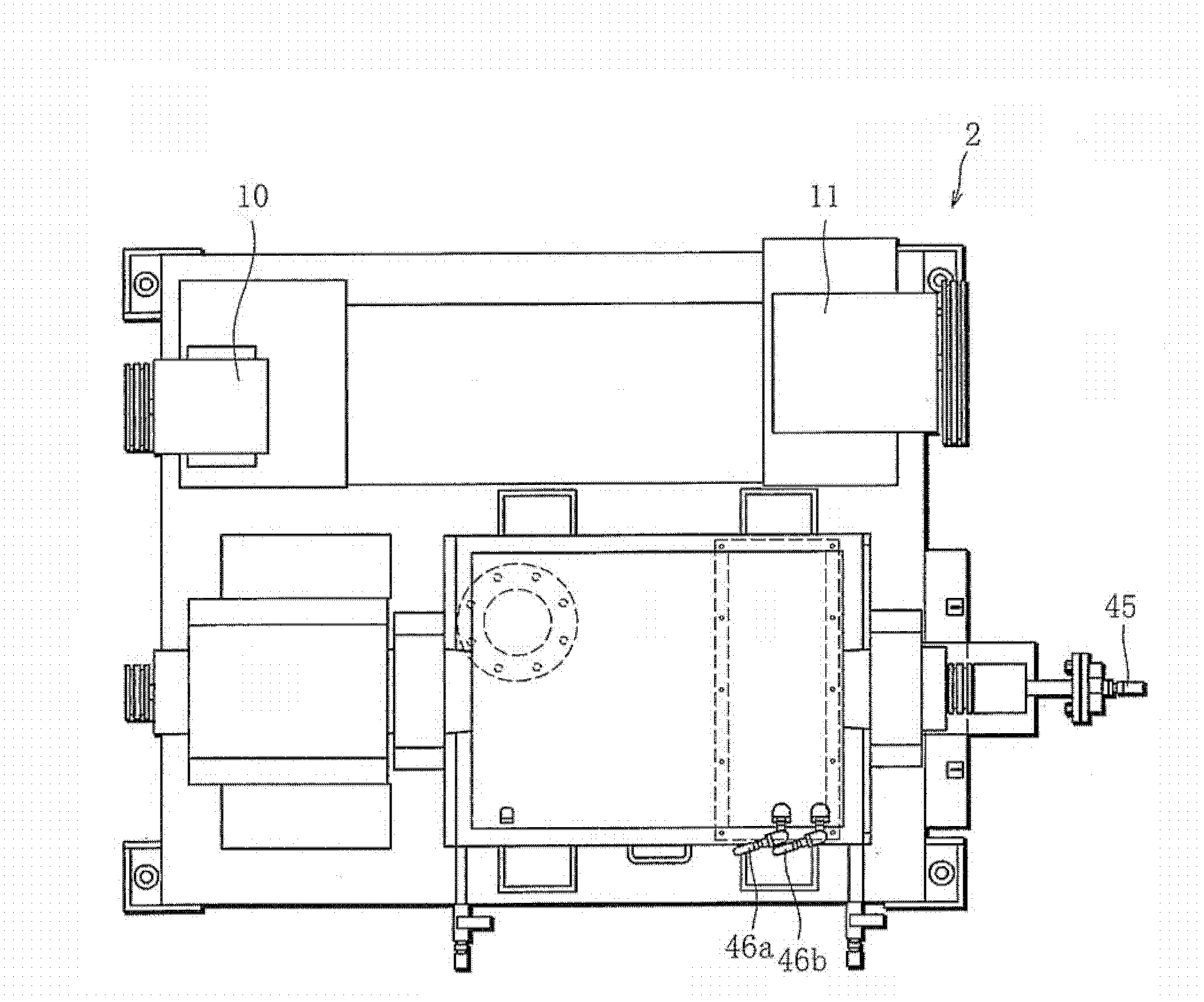
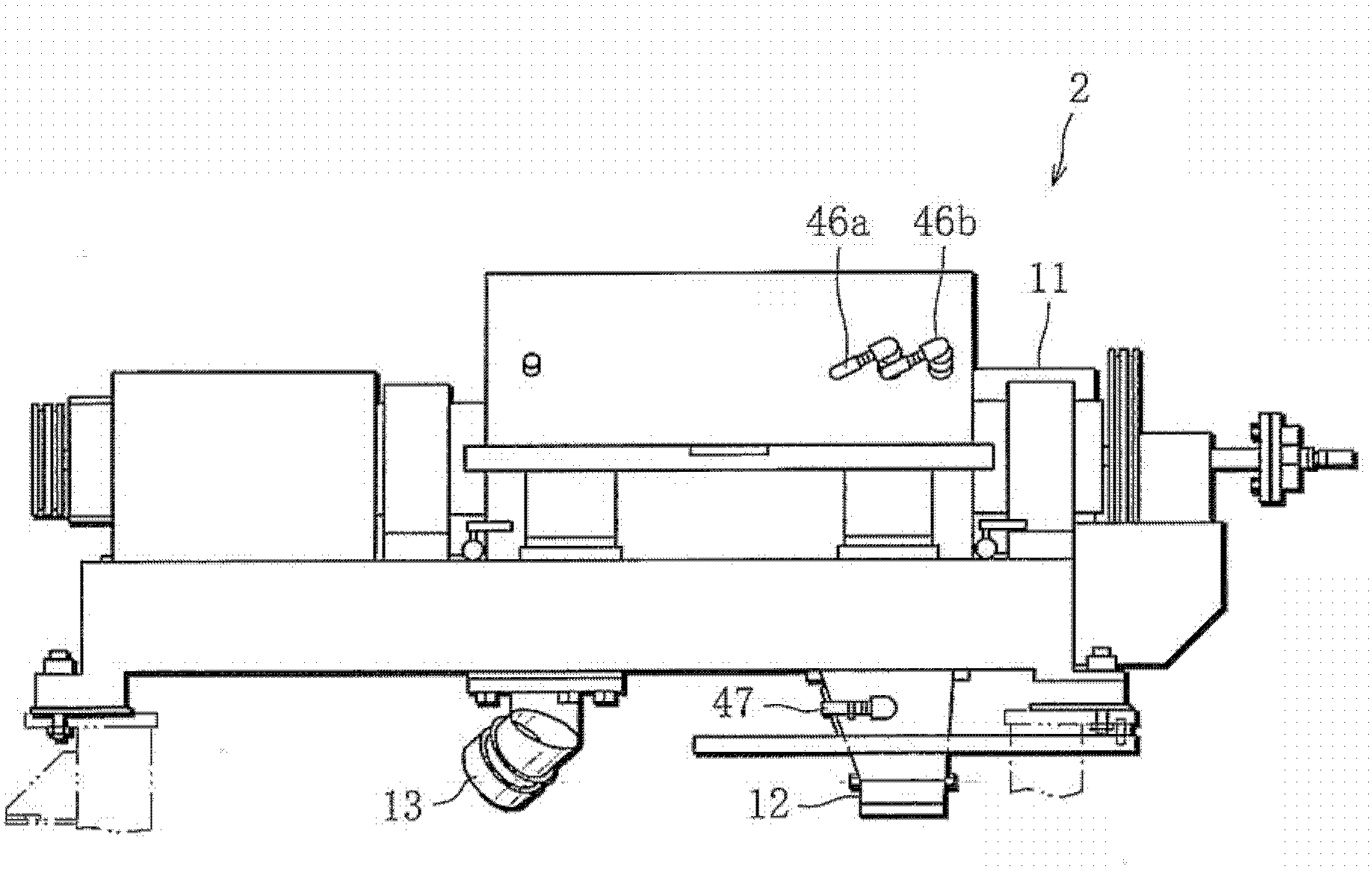
[0082] As shown in the figure, the slurry regeneration device 1 of the present invention is equipped with: a centrifugal separator 2, a first recovery tank 3 for recovering abrasive grains (primary separation), and a second recovery tank 3 for recovering cutting chips (secondary separation). Recovery tank 4, third recovery tank 5 for recovering dispersion medium, fourth recovery tank 6 for recovery of mixed liquid, blending tank 7 for blending regenerated slurry, branch tank 8, switching device 9. Each of the centrifugal separators 2 includes two motors (first motor 10 and second motor 11 ) capable of generating a centrifugal force different from low-G or high-G.

[0083] The waste slurry to be separated consists of abrasive grains, cutting chips (sludge), and dispersion medium (oil). Cutting chips are generated when a not-shown brittle material is cut and processed by a wire ...


PUM


Abstract

A slurry regenerating device provided with a centrifugal separator (2) for allowing waste slurry to be inserted therein, a discharge opening (12) for discharging a primarily separated substance and a secondarily separated substance from the centrifugal separator (2), a first collecting vessel (3) communicating with the discharge opening (12) through a route (8a) for the primarily separated substance, a second collecting vessel (4) communicating with the discharge opening (12) through a route (8b) for the secondarily separated substance, a liquid discharge opening (13) for discharging dispersed soot or a mixed liquid of the dispersed soot and the secondarily separated substance, a third collecting vessel (5) and a fourth collecting vessel (6) which communicate with the liquid discharge opening (13), a blending vessel (7) for generating regenerated slurry, and a switching means (9); for connecting either the route (8a) for the primarily separated substance or the route (8b) for the secondarily separated substance to the discharge opening (12).

Description

technical field [0001] The present invention relates to a regeneration device and method of slurry, in particular to a regeneration device and method of waste slurry after cutting of a wire saw device. Background technique [0002] Currently, in order to reduce costs, waste slurry discharged from processing equipment (for example, wire saw equipment, etc.) using slurry is recycled. The waste slurry of such a wire saw device consists of a dispersion medium, abrasive grains and cutting chips mixed therein. Such separation uses two centrifugal separators to separate abrasive grains and cutting chips from the dispersion medium. Specifically, the waste slurry is put into the first centrifugal separator, and abrasive grains having a specific gravity larger than cutting chips are first separated by a low centrifugal force of less than 1500G. Afterwards, the mixed liquid composed of dispersion medium and cutting chips is poured into the second centrifugal separator, and the cuttin...

Claims


Application Information

Patent Timeline
IPC IPC(8): B24B57/02H01L21/304
CPCB24B57/02B24B27/0633B28D5/007Y02P70/10H01L21/304
Inventor 百中幸久池永邦信绪方秀敏
Owner IHI ROTATING MACHINERY ENG CO LTD
Why Eureka
Try Eureka