
wind power equipment

A technology for wind power generation equipment and generators, which is applied in the directions of wind turbine components, wind energy power generation, wind turbines, etc., can solve the problems of affecting the life of the meshing part and other components, and the problems are not good.

Active Publication Date: 2011-12-14
IMO HOLDING GMBH
View PDF4 Cites 12 Cited by
  • Summary
  • Abstract
  • Description
  • Claims
  • Application Information

AI Technical Summary

Problems solved by technology

Compared with the critical load (Schwellast), this switching load affects the life of the meshing part and other components more badly

Method used


Image

  • wind power equipment
  • wind power equipment
  • wind power equipment

Examples


Embodiment Construction

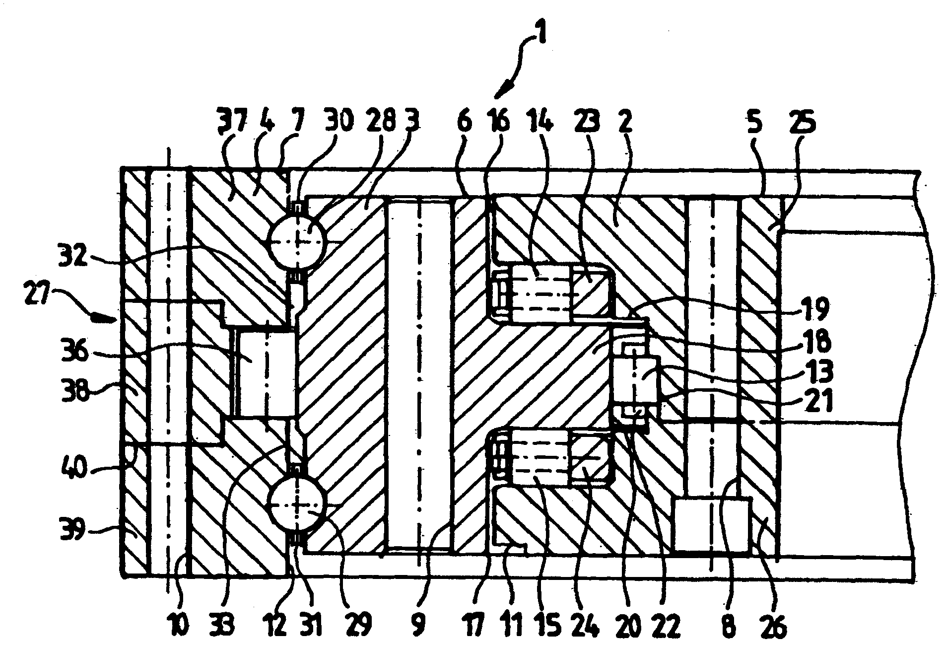
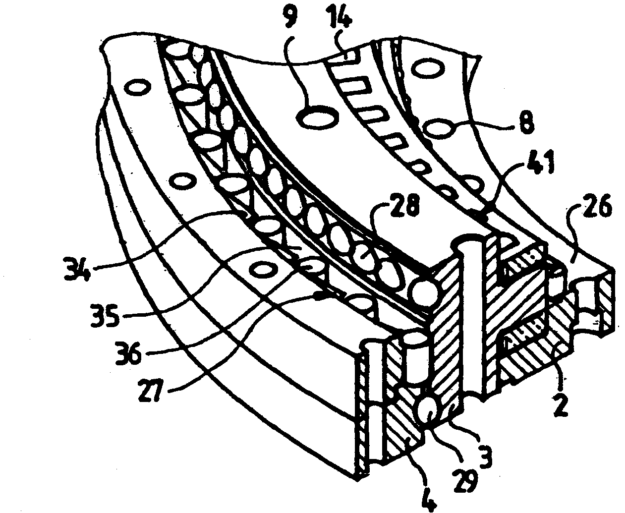
[0043] exist figure 1 2 shows, by way of example for the present invention, a sectional view of a ring of a rolling bearing 1 for a rotor of a wind power plant having a rotor with an axis of rotation pointing approximately in the direction of the wind. The rolling bearing 1 can be used as a main bearing of a wind power plant, and the rolling bearing 1 also carries the rotor hub; especially when the wind power plant is not driven, the bearing 1 can also be used as a bearing for guiding the rotor shaft, or the bearing 1 Interlock (Anschluβ) connected to the transmission or coupling of the drive train from the wind rotor to the generator - especially on the output

[0044] The bearing 1 comprises three rings 2 , 3 , 4 which are each relatively rotatable. exist figure 1 In the example in , the inner ring 2 is fixed on the frame of the machine housing, the middle ring 3 is connected to the rotor hub or rotor shaft or to the output of the transmission or coupling, and the outer ri...


PUM


Abstract

The invention is directed to a wind power plant having a rotor mounted rotatably about an axis directed approximately in the wind direction, and having at least two mutually concentric annular elements for connection to oppositely rotatable system components of the wind power plant, one of which comprises means for connection to the rotor of the wind power plant or to a drive shaft of a gearbox coupled thereto; at least one element having a freewheel characteristic is disposed between the two connection elements and together with them forms a freewheel, at least one connection element being provided with at least one integrated raceway for a row of rolling bodies rolling thereon.

Description

technical field [0001] The invention relates to a wind power plant having a rotor mounted rotatably about an axis generally directed in the wind direction, at least two annular elements concentric with each other for connection to the wind power plant On the parts of the equipment that can be rotated relative to each other, one of the said elements has a connection to the rotor of the wind power plant or to the driven shaft of the transmission coupled to the rotor or to a coupling connected to the rotor above institutions. Background technique [0002] Wind power plants are mostly exposed to very irregular wind conditions and are therefore subject to strong load fluctuations, which result in a particularly high number of load changes in the rotor and downstream components (in particular the transmission and the generator) . Such continuously changing load loading adversely affects the fatigue strength of the associated components. [0003] Attempts have therefore been mad...

Claims


Application Information

Patent Timeline
Patent Type & Authority Applications(China)
IPC IPC(8): F03D9/00F03D11/00F03D11/02F03D7/00
CPCY02E10/72Y02E10/723F16C19/545F03D11/0008F03D7/0204F16C2360/31Y02E10/722F16C19/381F16C19/49F16C19/50F16C19/54F16C41/001F16C2300/14F03D80/70F16C19/55
Inventor 胡贝图斯·弗兰克
Owner IMO HOLDING GMBH
Learn More