Liquid crystal display device

A liquid crystal display device, liquid crystal display panel technology, applied in nonlinear optics, instruments, optics, etc., can solve the problems of reduced transmittance, blurred characters, etc.

Active Publication Date: 2011-12-14
SHARP KK
View PDF10 Cites 12 Cited by
  • Summary
  • Abstract
  • Description
  • Claims
  • Application Information

AI Technical Summary

Problems solved by technology

[0009] However, in the method described in Patent Document 1, since there are three polarizing layers, the transmittance is greatly reduced.
In addition, in the method described in Patent Document 2, since an anisotropic scattering layer is disposed on the display surface, the display is easily affected by external light and characters are blurred. In addition, characters are blurred by the scattering layer.
In this way, there is no technology that can improve the viewing angle characteristics without using a special compensation layer or a scattering layer, and there is still room for improvement.

Method used


Image

  • Liquid crystal display device
  • Liquid crystal display device
  • Liquid crystal display device

Examples


Embodiment approach 1

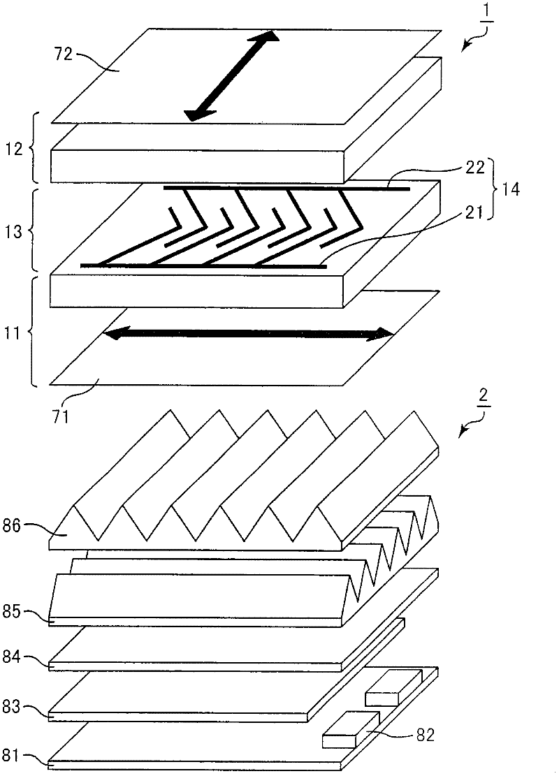
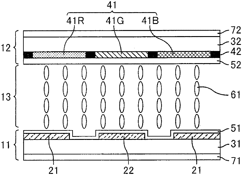
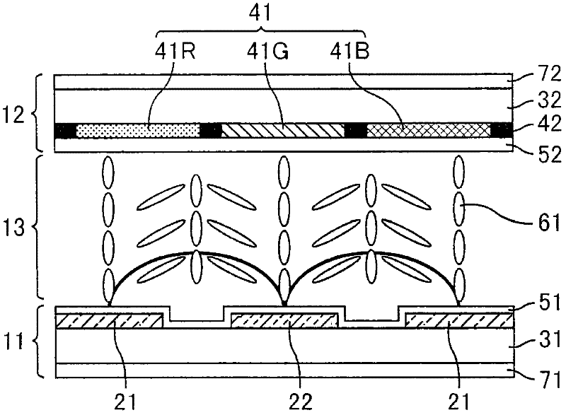
[0068] figure 1 It is a schematic perspective view of the liquid crystal display device of the first embodiment. The liquid crystal display device according to Embodiment 1 includes a liquid crystal display panel 1 having a liquid crystal layer 13 and a pair of substrates 11 and 12 sandwiching the liquid crystal layer 13 . More specifically, the liquid crystal display device according to Embodiment 1 includes components such as a TFT substrate 11 , a liquid crystal layer 13 , and a counter substrate 12 in this order from the rear side toward the observation side. The liquid crystal layer 13 contains a nematic liquid crystal having positive dielectric constant anisotropy (Δε>0). In addition, the liquid crystal display device according to Embodiment 1 includes a backlight unit 2 on the rear side of the liquid crystal display panel 1 .

[0069] Such as figure 1 As shown, the TFT substrate 11 in the above pair of substrates has a pair of comb-shaped electrodes 14 that are spa...

Embodiment approach 2

[0095] Figure 6 It is a schematic cross-sectional view of a backlight unit included in the liquid crystal display device according to the second embodiment. The liquid crystal display device of Embodiment 2 has the same configuration as Embodiment 1 except for the configuration of the backlight unit. Such as Figure 6 As shown, the backlight unit included in the liquid crystal display device according to Embodiment 2 includes a reflection sheet 81 , a light source 82 , a light guide plate 83 , and a third lens sheet 87 . Of these members, the reflective sheet 81 is arranged on the rearmost side, and the light guide plate 83 is arranged on the reflective sheet 81 (on the observation surface side of the reflective sheet). In addition, a light source 82 is arranged on the side of the light guide plate 83 so that the light emitting direction faces the light guide plate 83 , and a third lens sheet 87 is arranged on the light guide plate 83 to face the light guide plate 83 . In ...

Embodiment approach 3

[0100] Figure 8 It is a schematic cross-sectional view of a backlight unit included in a liquid crystal display device according to Embodiment 3. FIG. The liquid crystal display device of Embodiment 3 has the same configuration as Embodiment 1 except for the configuration of the backlight unit. Such as Figure 8 As shown, the backlight unit included in the liquid crystal display device according to Embodiment 3 includes a reflection sheet 81 , a light source 82 , a diffusion plate 88 , a diffusion sheet 84 , a first lens sheet 85 , and a second lens sheet 86 . Of these members, the reflective sheet 81 is arranged on the rearmost side, and the light source 82 is arranged on the reflective sheet 81 (on the observation surface side of the reflective sheet). In addition, a diffusion plate 88 , a diffusion sheet 84 , a first lens sheet 85 , and a second lens sheet 86 are sequentially arranged above the light source 82 . Like the diffusion sheet 84 , the diffusion plate 88 diffu...


PUM


Abstract

Disclosed is a liquid crystal display device of which viewing angle characteristics are improved without reducing the transmittance. Specifically disclosed is a liquid crystal display device which comprises a liquid crystal display panel including a liquid crystal layer and a pair of substrates that hold the liquid crystal layer therebetween and a backlight unit disposed at the rear side of the liquid crystal display panel. One of the pair of substrates is provided with a pair of comb-shaped electrodes of which comb teeth alternately engage with each other with a gap interposed therebetween. The liquid crystal layer includes liquid crystal molecules with positive dielectric anisotropy, and the liquid crystal molecules are oriented perpendicular to a surface of the one of the substrates while voltage is not applied. A difference between the proportion of the liquid crystal molecules oriented at angles of 20 DEG to 60 DEG and -60 DEG to -20 DEG with respect to the surface of the one of the substrates to the entire liquid crystal molecules included in the liquid crystal layer while white is displayed and the proportion of light beams entering the surface of the one of the substrates at angles of 20 DEG to 60 DEG and -60 DEG to -20 DEG to the entire light beams emitted from the backlight unit and entering the liquid crystal display panel is less than 20%.

Description

technical field [0001] The present invention relates to a liquid crystal display device. More specifically, it relates to a liquid crystal display device suitable for a display method in which the initial alignment of liquid crystal molecules is vertical alignment and the mode of liquid crystal molecules is controlled by generating an electric field (for example, a lateral electric field). Background technique [0002] Liquid crystal display devices are characterized by thinness, light weight, and low power consumption, and are widely used in various fields. In general, a liquid crystal display device is provided with a backlight unit for display, and light emitted from the backlight unit is controlled by liquid crystals. [0003] As a light source, sunlight can also be reflected and used in displays. Liquid crystal display devices such as word processors, notebook personal computers, and vehicle displays are mainly used indoors, or a certain amount of light is often requir...

Claims


Application Information

Patent Timeline
Patent Type & Authority Applications(China)
IPC IPC(8): G02F1/13357G02F1/1343
CPCG02F1/134363G02F2001/13706G02F2001/133742G02F1/133742G02F1/13706
Inventor 村田充弘石原将市神崎修一樱井猛久大竹忠
Owner SHARP KK
Why Eureka
Try Eureka