Method and related apparatus for reducing pressure in a loadlock

A technology of load lock and pressure, applied in mechanical equipment, transportation and packaging, ion implantation and plating, etc., can solve the problems of complex implementation of driving devices, reliability problems of turbomolecular pumps, and high pumping noise.

Inactive Publication Date: 2011-12-14
ADIXEN VACUUM PRODUCTS
View PDF1 Cites 4 Cited by
  • Summary
  • Abstract
  • Description
  • Claims
  • Application Information

AI Technical Summary

Problems solved by technology

However, pumping from atmospheric pressure using a turbomolecular pump has been found to create reliability issues with the turbomolec

Method used


Image

  • Method and related apparatus for reducing pressure in a loadlock
  • Method and related apparatus for reducing pressure in a loadlock
  • Method and related apparatus for reducing pressure in a loadlock

Examples


Embodiment Construction

[0034] The term "main vacuum pressure" means a pressure of less than about 0.1 Pascal obtained by main pumping. The term "secondary vacuum pressure" refers to a pressure of less than about 0.1 Pascal obtained by secondary turbomolecular pumping.

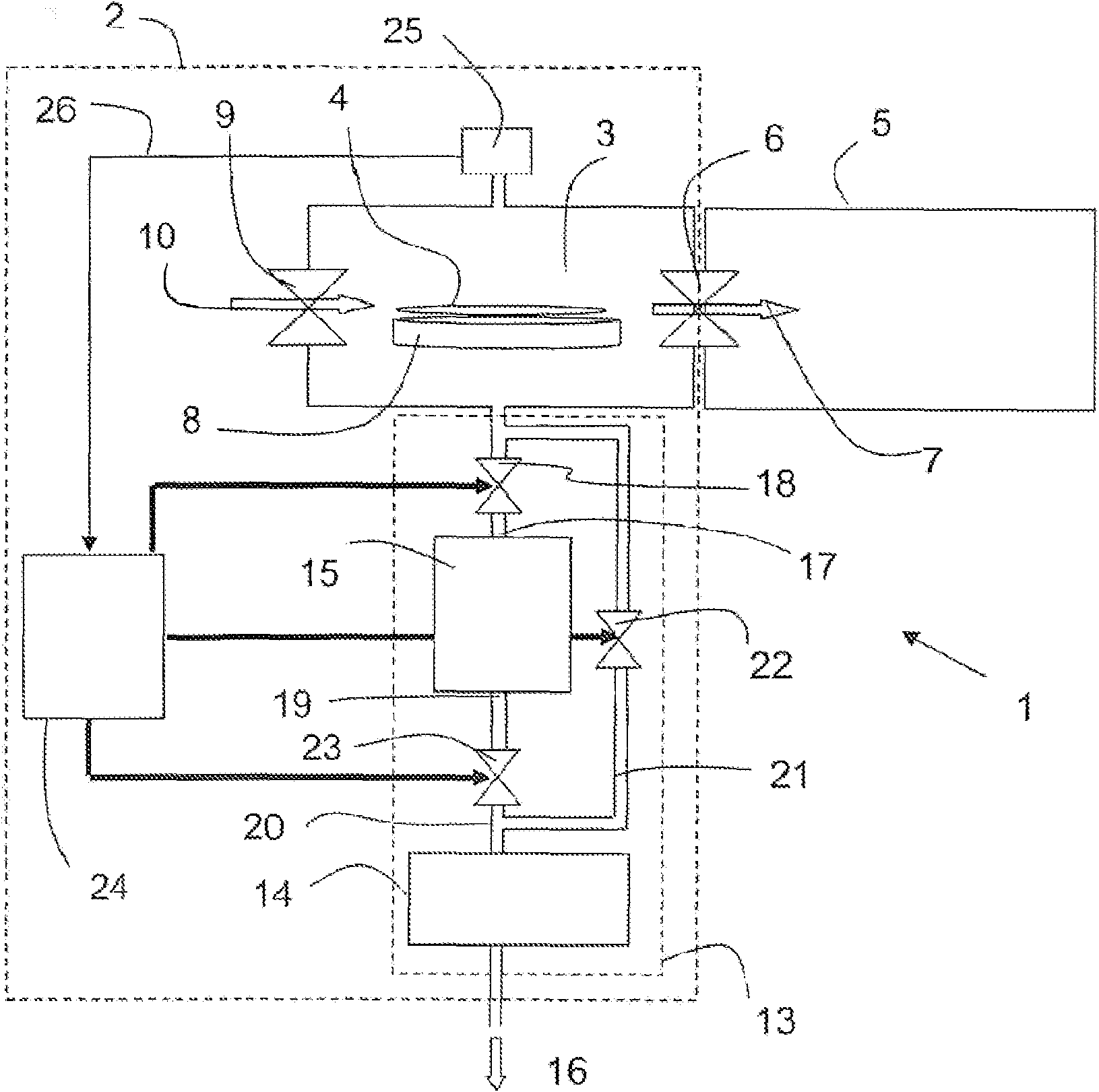
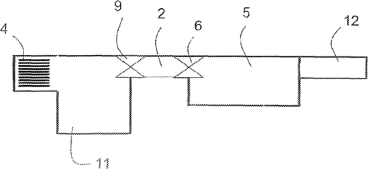
[0035] figure 1 Shown is an apparatus 1 comprising a load lock 2 comprising a chamber 3 for reducing the ambient pressure of at least one substrate 4 from atmospheric pressure to a sub-atmospheric transfer pressure.

[0036] A subatmospheric delivery pressure is, for example, a main vacuum pressure of about 0.01 Pascal.

[0037] The apparatus 1 also comprises at least one process chamber 5 communicating with the load lock 2 via a first lock door 6 for transferring substrates 4 in the direction of arrow 7 into the process chamber 5 under transfer pressure.

[0038] The load lock 2 and the processing chamber 5 comprise a substrate carrier 8 and a robot (not shown) in particular for supporting and transporting the substrate 4 .

[00...


PUM


Abstract

The present invention relates to a method for reducing the pressure in an equipment load lock from atmospheric pressure to a sub-atmospheric transfer pressure, said lock comprising a chamber in which at least one substrate is placed at atmospheric pressure, said method comprising: a first step (101), wherein a first main pumping from atmospheric pressure to a first characteristic threshold is performed with a pumping rate limited main pump while isolating turbomolecular pumping from the chamber; after the first step (101) A second step (102) of wherein a second main pumping to a second characteristic threshold faster than in said first step is performed while maintaining isolation of turbomolecular pumping; said second step (102) A third step (103) follows, wherein secondary pumping is performed by means of said turbomolecular pumping upstream of said first pumping, and said chamber is isolated from said primary pump. The invention also relates to a device for carrying out the method.

Description

technical field [0001] The present invention relates to a method for reducing the pressure in a substrate load lock from atmospheric pressure to a low pressure to load and unload a substrate into a process chamber maintained at low pressure. The invention also relates to a device suitable for carrying out the method, for example for the manufacture of semiconductor components, comprising a load lock. Background technique [0002] Some fabrication methods include an important step in which the substrate is processed in a controlled atmosphere at very low pressure in the process chamber of the device. For example, in a semiconductor element manufacturing method, it is desirable to keep a semiconductor substrate under a very low pressure to perform plasma etching or deposition. [0003] In order to maintain acceptable production rates and avoid the appearance of any impurities or contamination, the atmospheric pressure surrounding the substrate is initially reduced to a lower ...

Claims


Application Information

Patent Timeline
IPC IPC(8): H01L21/677H01L21/00C23C14/00
CPCF04D19/04H01L21/67201Y10T137/0396Y10T137/86171H01L21/67109
Inventor J·布努阿尔J-M·福雷
Owner ADIXEN VACUUM PRODUCTS
Why Eureka
Try Eureka