
Double rope groove multi-layer hoisting mechanism

A lifting mechanism and rope groove technology, which is applied in the field of double rope groove multi-layer lifting mechanism, can solve the problems that have not been found in the same or similar literature reports of window cleaning machines, and achieve simple structure, no rope disorder, and flexible operation Effect

Inactive Publication Date: 2011-12-21
SHANGHAI POINT HIGH RISE EQUIP
View PDF6 Cites 4 Cited by
  • Summary
  • Abstract
  • Description
  • Claims
  • Application Information

AI Technical Summary

Problems solved by technology

[0003] In the conventional design of the lifting mechanism of the window cleaning machine, because the window cleaning machine is mainly designed for high floors, the lifting height of the lifting mechanism is generally high, and the multi-rope groove multi-layer lifting mechanism is the main one. As people's requirements for the environment are getting higher and higher, window cleaning machines are gradually installed on low and medium building floors. However, due to the constraints of conventional thinking, the lifting mechanism of window cleaning machines has been using the early design. Our company According to the height requirements of the building floors, a special hoisting mechanism for low-rise buildings has been specially developed. Compared with the previous hoisting mechanisms, this hoisting mechanism has a simple and simple transmission mode, and there is no disadvantage of rowing and tangled ropes. Rope groove single-row multi-layer winding hoisting mechanism, its manufacturing cost and reliability are improved
[0004] After checking the novelty of the prior art, it has not been found that there are any literature reports identical or similar to the subject of the present invention in the field of window cleaning machines

Method used


Image

  • Double rope groove multi-layer hoisting mechanism
  • Double rope groove multi-layer hoisting mechanism
  • Double rope groove multi-layer hoisting mechanism

Examples


Embodiment Construction

[0021] The embodiments of the present invention are described in detail below in conjunction with the accompanying drawings: this embodiment is implemented on the premise of the technical solution of the present invention, and detailed implementation methods and specific operating procedures are provided, but the protection scope of the present invention is not limited to the following the described embodiment.

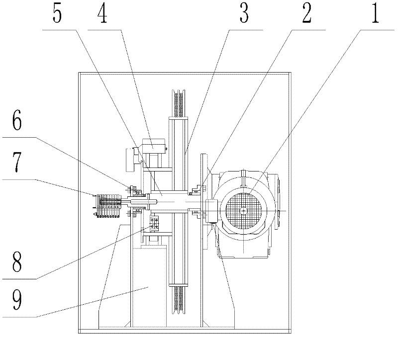
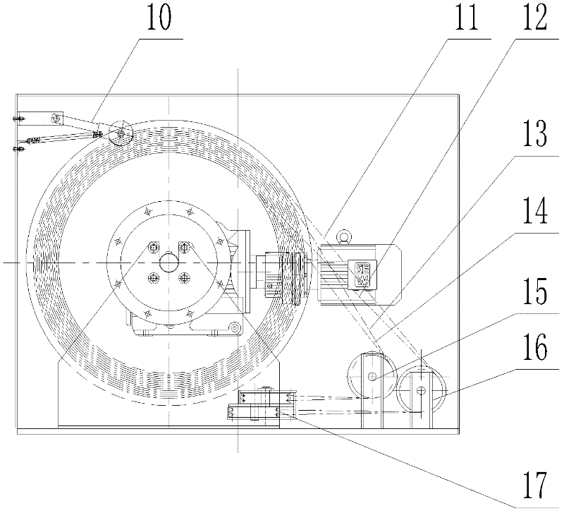
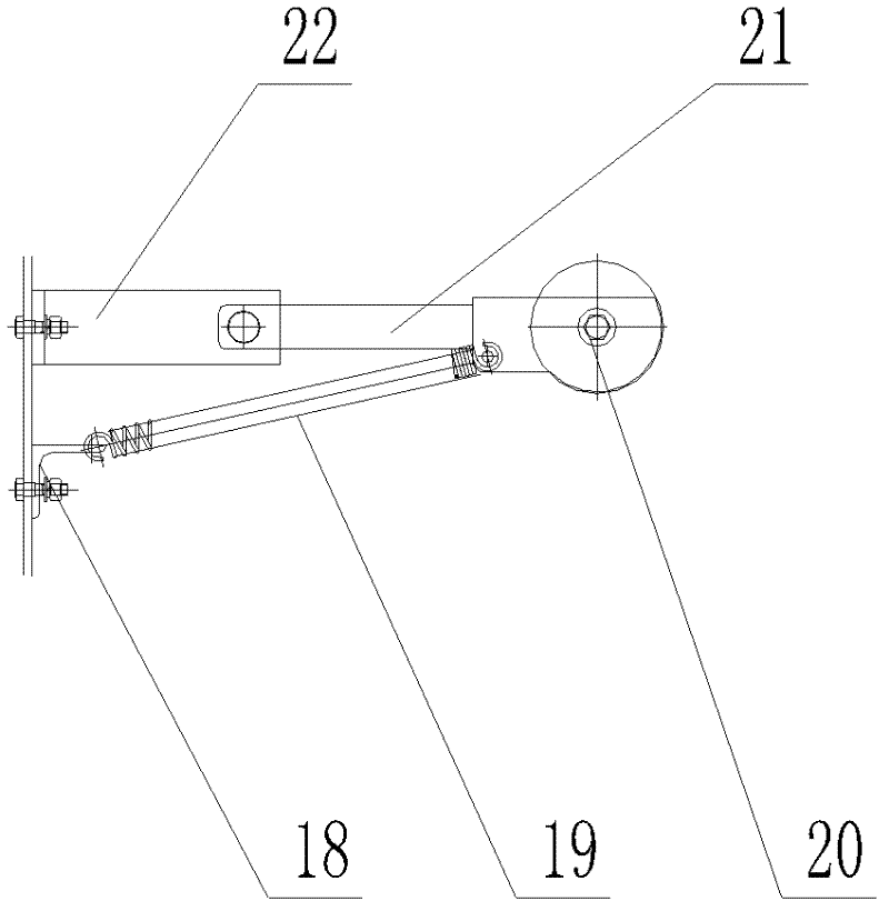
[0022] Such as figure 1 , figure 2 As shown, the overall structure of the present invention includes: geared motor 1, right bearing housing 2, reel main body 3, brake 4, main transmission shaft 5, left bearing housing 6, carbon brush assembly 7, wire rope clamp assembly 8, reel Support frame 9, pressure rope device 10, steel wire rope 11, steel wire rope 12, steel wire rope 13, steel wire rope 14, left vertical pulley 15, right vertical pulley 16, horizontal pulley block 17. The relevant positional relationship and connection relationship are as follows: the reduct...


PUM


Abstract

The invention relates to a mechanical device in the technical field of building exterior wall cleaning, in particular to a double-rope groove multi-layer hoisting mechanism specially used in a window cleaning machine system. The invention mainly includes a reel supporting frame, a left bearing seat and a right bearing seat, a reel main body, a reduction motor, a left vertical pulley and a right vertical pulley, and a horizontal pulley block. The main transmission shaft of the reel is directly driven by the geared motor, and double rope grooves are used for winding, which avoids the problem of wire rope arranging, and through the effective installation of vertical pulleys, each wire rope in the two rope grooves is wound into the same A vertical pulley makes the steel wire rope passing through the first set of pulleys become the guide rope of the second set of pulleys, completely eliminating the need to use other third-party mechanisms to arrange the ropes, eliminating the phenomenon of rope chaos. Compared with the existing lifting mechanism, the lifting mechanism has the advantages of simple structure, flexible operation, safety and reliability.

Description

technical field [0001] The invention relates to a mechanical device in the technical field of building exterior wall cleaning, in particular to a double-rope groove multi-layer hoisting mechanism specially used in a window cleaning machine system. Background technique [0002] With the rapid development of China's economy, China's construction machinery industry has also made leaps and bounds. It has changed from mainly relying on foreign technology in the early stage to mainly relying on independent research and development. Gradually form an industry with a unique system. As window cleaning machines become more and more familiar to people, the demand for window cleaning machines in the Chinese market is increasing, and more companies are constantly joining this industry. Therefore, the competition in the industry is becoming more and more fierce. [0003] In the conventional design of the lifting mechanism of the window cleaning machine, because the window cleaning machin...

Claims


Application Information

Patent Timeline
Patent Type & Authority Applications(China)
IPC IPC(8): A47L11/40A47L11/38A47L1/02B66D1/00B66D1/36
Inventor 谢建琳蒯文龙兰阳春
Owner SHANGHAI POINT HIGH RISE EQUIP
Learn More