Al technical title is built by PatSnap Al team. It summarizes the technical point description of the patent document.
A technology of stirring device and suspension arm, which is applied to mixers with rotary stirring devices, accessories of mixers, chemical/physical/physical-chemical stationary reactors, etc., can solve the problem that sludge cannot be effectively stirred, sludge hardness increases, Increase the motor load and other problems, to achieve the effect of improving the chemical reaction efficiency, easy cleaning, and reducing the load
Inactive Publication Date: 2011-12-21
杨升华
View PDF3 Cites 5 Cited by
Summary
Abstract
Description
Claims
Application Information
AI Technical Summary
This helps you quickly interpret patents by identifying the three key elements:
Problems solved by technology
Method used
Benefits of technology
Problems solved by technology
[0002] Most of the existing sludge mixing devices install a large agitator in the mixing tank or mixing tank to mix the sludge as a whole. This kind of agitation requires the agitator to be driven by a high-power motor, which consumes a lot of energy and the sludge is dry. After the hardness increases, the resistance during stirring is relatively large, which increases the load on the motor and is easy to burn out the motor. In addition, there is a large dead angle of stirring between the existing agitator and the mixing tank or mixing pool, and the sludge in the dead angle cannot be effectively obtained. Stirring, extremely difficult to clean up after drying
Method used
Image
Click on the blue label to locate the original text in one second.
Reading with bidirectional positioning of images and text.
Examples
Embodiment Construction
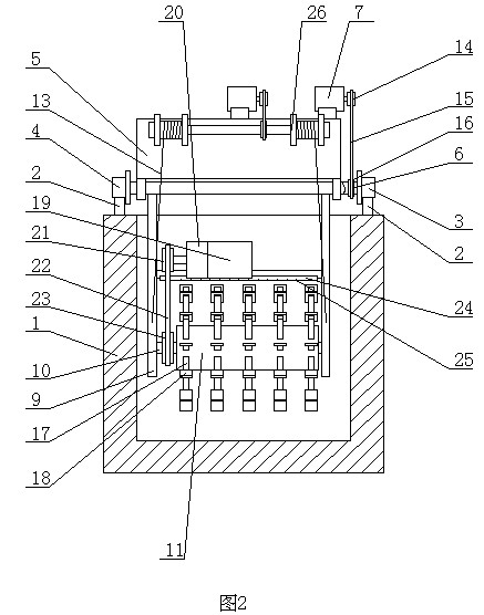
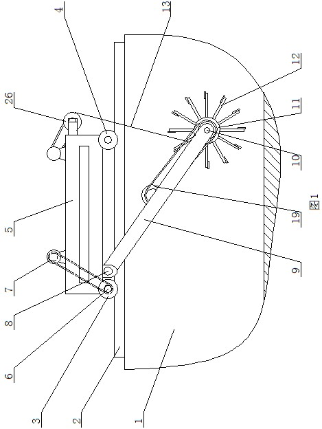
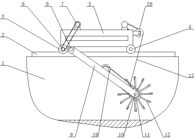
[0007] The hanging arm type sludge stirring device of the present invention comprises a stirring tank 1, guide rails 2 are arranged on both sides of the top of the stirring tank 1, a driving wheel 3 and a driven wheel 4 are installed on the guide rail 2, and the driven wheel 4 is installed on a walking frame 5, and the driving The wheels 3 are connected through the drive shaft 6, the drive shaft 6 is connected with the travel motor 7 through the travel transmission device, the hinge shaft 8 is installed at the bottom of the travel frame 5, the two sides of the hinge shaft are hinged with the upper end of the cantilever 9, and the stirring shaft is installed at the lower end of the cantilever 9 10. The stirring roller 11 is installed on the stirring shaft 10, the stirring teeth 12 are arranged on the stirring roller 11, the stirring motor 19 is installed on the cantilever 9, the stirring motor 19 is connected with the stirring shaft 10 through the stirring transmission device, th...
PUM
Abstract
The invention discloses a suspension arm type sludge stirring device, which comprises a stirring tank, guide rails are arranged on both sides of the top of the stirring tank, a driving wheel and a driven wheel are installed on the guide rail, the driven wheel is installed on a walking frame, and a driving shaft is passed between the driving wheels Connection, the drive shaft is connected with the travel motor through the travel transmission device, the hinge shaft is installed at the lower part of the travel frame, the two sides of the hinge shaft are hinged with the upper end of the cantilever, the stirring shaft is installed at the lower end of the cantilever, the stirring roller is installed on the stirring shaft, and the stirring teeth are set on the stirring roller , A stirring motor is installed on the cantilever, the stirring motor is connected to the stirring shaft through a stirring transmission device, a hoist is installed on the walking frame, and the hoist is connected to the cantilever through a noose. The present invention can adjust the position of the agitator according to the needs, carry out stratification and regional agitation of the sludge, does not need to be driven by a high-power motor, reduces energy consumption, and is beneficial to reduce the load of the motor, prevents the motor from burning out, and can agitate The sludge everywhere in the pool is evenly stirred, there is no mixing dead angle, and the sludge is easy to clean.
Description
technical field [0001] The invention relates to a sludge treatment device, in particular to a hanging arm type sludge stirring device. Background technique [0002] Most of the existing sludge mixing devices install a large agitator in the mixing tank or mixing tank to mix the sludge as a whole. This kind of agitation requires the agitator to be driven by a high-power motor, which consumes a lot of energy and the sludge is dry. After the hardness increases, the resistance during stirring is relatively large, which increases the load on the motor and is easy to burn out the motor. In addition, there is a large dead angle of stirring between the existing agitator and the mixing tank or mixing pool, and the sludge in the dead angle cannot be effectively obtained. Agitates and is extremely difficult to clean up once dry. Contents of the invention [0003] The purpose of the present invention is to provide a hanging arm type sludge stirring device, which can adjust the positio...
Claims
Application Information
Patent Timeline
Application Date:The date an application was filed.
Publication Date:The date a patent or application was officially published.
First Publication Date:The earliest publication date of a patent with the same application number.
Issue Date:Publication date of the patent grant document.
PCT Entry Date:The Entry date of PCT National Phase.
Estimated Expiry Date:The statutory expiry date of a patent right according to the Patent Law, and it is the longest term of protection that the patent right can achieve without the termination of the patent right due to other reasons(Term extension factor has been taken into account ).
Invalid Date:Actual expiry date is based on effective date or publication date of legal transaction data of invalid patent.