A split air-air heat exchange unit with a humidification section

An air heat exchange, split-type technology, applied in heating methods, air humidification systems, lighting and heating equipment, etc., can solve the problems of low enthalpy value, insufficient utilization of air energy, and insufficient utilization of air energy.

Inactive Publication Date: 2011-12-21
BEIJING UNIV OF TECH
View PDF3 Cites 10 Cited by
  • Summary
  • Abstract
  • Description
  • Claims
  • Application Information

AI Technical Summary

Problems solved by technology

The existing air-to-air heat exchange units only use the sensible heat of the two streams of air. For some areas, such as Beijing, Gansu, Inner Mongolia and other areas, although the outdoor air is high, the relative humidity is low and the enthalpy is low. The characteristics of the air have not been fully utilized, that is to say, the ener

Method used


Image

  • A split air-air heat exchange unit with a humidification section
  • A split air-air heat exchange unit with a humidification section
  • A split air-air heat exchange unit with a humidification section

Examples


Embodiment 1

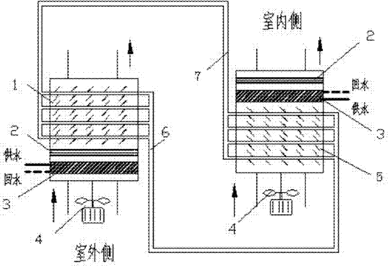
[0017] Example 1: A thermosiphon split air-to-air heat exchanger (without pump) with a humidification section using a natural cold source to cool down the computer room

[0018] Such as figure 1 As shown, a thermosiphon split air-to-air heat exchanger with a humidification section, the heat exchanger is a thermosiphon split heat exchanger without a pump. The condenser and the evaporator are connected together through the gas collecting pipe and the liquid collecting pipe. When installing, ensure that the height of the evaporator is lower than the condenser. Return to the evaporator through the height difference. Condenser, evaporator, gas collection pipe and liquid collection pipe form a closed space, after sealing, vacuumize, and then fill the inside with 30% low boiling point phase change medium. Based on the evaporator, the air duct is fixedly connected at the air inlet and outlet of the evaporator to form a closed indoor air duct. The inlet and outlet of the air duct com...

Embodiment 2

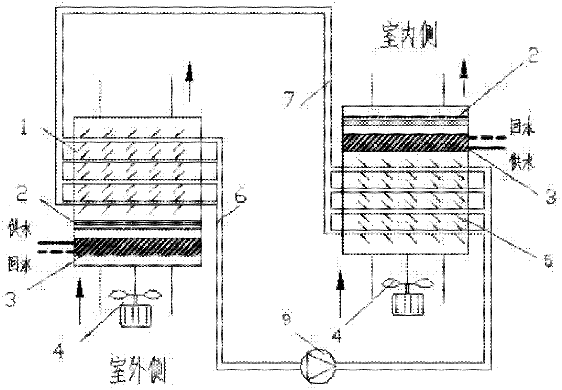
[0019] Embodiment 2: A thermosiphon split air-to-air heat exchanger (with a liquid pump) with a humidification section using a natural cold source to cool down the machine room

[0020] Such as figure 2 As shown, a thermosiphon split air-to-air heat exchanger with a humidification section, the heat exchanger is equipped with a liquid pump, the condenser and the evaporator are connected together through the gas collection pipe and the liquid collection pipe, and the liquid collection pipe A liquid pump is installed on the top, and through external force, it can overcome the problem that the height of the condenser must be higher than that of the evaporator. Its working mode is the same as that of the first embodiment.

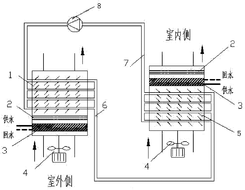
[0021] attached image 3 : Embodiment Three—Using natural cold source to carry out the thermosiphon type split air-air heat exchanger (with air pump) with humidification section for the machine room to cool down

[0022] Such as image 3 As shown, a thermos...


PUM


Abstract

A split-type air-air heat exchange unit with a humidification section relates to a device used in an air-conditioning system to reduce temperature by using a natural cold source, and belongs to the technical field of heat exchange of heat devices. On the basis of the existing split air-air heat exchange unit, the present invention adds an air humidification section at the outdoor air inlet and indoor air outlet, so that the outdoor low-temperature air first flows through the humidification section for humidification, and the humidity is increased through humidification After the temperature is lowered, heat exchange is performed. Compared with the heat exchange equipment without the low-temperature air humidification section, the heat exchange temperature difference on both sides of the air heat exchanger is enlarged, the heat exchange amount is increased, and the heat exchange efficiency is improved. In addition, an air humidification section is added at the indoor air outlet, which can humidify the air as needed, control the relative humidity of the air within the required range, prevent static electricity, and improve the comfort of the air environment.

Description

1. Technical field [0001] The invention relates to a device used in an air-conditioning system to lower the temperature by using a natural cold source, and belongs to the technical field of heat exchange of thermal devices. 2. Background technology [0002] Energy-saving and low-carbon is the theme of social development today. In the field of refrigeration and air-conditioning, people have been practicing the concept of low-carbon, exploring ways to save energy and reduce emissions, and research and develop related energy-saving technologies, especially technologies that reduce air-conditioning energy consumption through efficient heat exchange. , so as to save energy as much as possible on the premise of meeting the air environment requirements of people or equipment. Existing air-to-air heat exchange units only use the sensible heat of two streams of air. For some areas, such as Beijing, Gansu, Inner Mongolia and other areas, although the outdoor air is high, the relative ...

Claims


Application Information

Patent Timeline
IPC IPC(8): F24F5/00F24F6/12
CPCY02B30/545Y02B30/54
Inventor 马国远张双
Owner BEIJING UNIV OF TECH
Why Eureka
Try Eureka