
Marine two-stage dehumidification and air-conditioning system with rotary wheels and its operation method

A technology of dehumidification and air-conditioning system with a rotary wheel, which is applied in the direction of air-conditioning systems, applications, heating methods, etc. It can solve the problems of unsuitable waste heat recovery and utilization of ships, and unfavorable air with high temperature and humidity, so as to save energy for regeneration and cooling, The effect of reducing carbon emissions

Active Publication Date: 2011-12-21
海英荷普曼船舶设备(常熟)有限公司
View PDF4 Cites 19 Cited by
  • Summary
  • Abstract
  • Description
  • Claims
  • Application Information

AI Technical Summary

Problems solved by technology

The defects and shortcomings of this patented technology are: the desiccant in the desiccant rotor in the device is regenerated and directly enters the dehumidification area, and a large amount of high-temperature and high-humidity gas remains in the air passage of the desiccant rotor, which is not conducive to dealing with the temperature and humidity in the marine environment Higher air; the evaporative cooler in the device is only suitable for use in a relatively stable environment on land, not suitable for use when the ship is shaking; the regenerative heat source in the device is a low-grade heat source such as solar energy, which is not suitable for high-grade of ship waste heat is recycled

Method used


Image

  • Marine two-stage dehumidification and air-conditioning system with rotary wheels and its operation method
  • Marine two-stage dehumidification and air-conditioning system with rotary wheels and its operation method
  • Marine two-stage dehumidification and air-conditioning system with rotary wheels and its operation method

Examples


Embodiment Construction

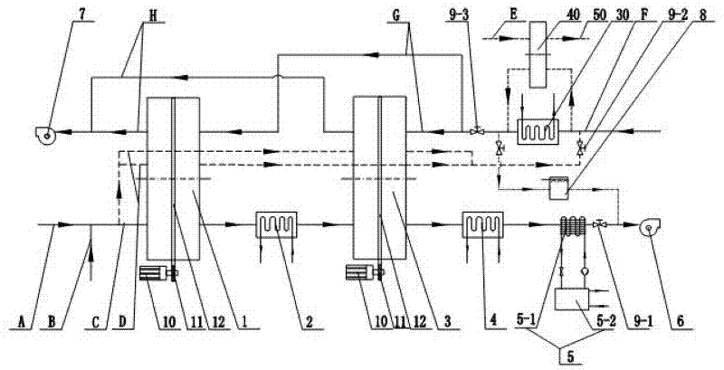
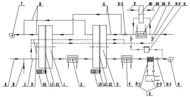
[0022] like figure 1 As shown, the present invention is a two-stage dehumidification and air-conditioning system for ships, which includes a first-stage dehumidification runner 1, a first-stage intercooler 2, a second-stage dehumidification runner 3, and a second-stage intercooler 4 , Compression air conditioner unit 5, processing fan 6, regeneration fan 7, humidifier 8, motor 10, gear 11, chain 12, waste heat heater 30, waste gas heat exchange wheel 40.

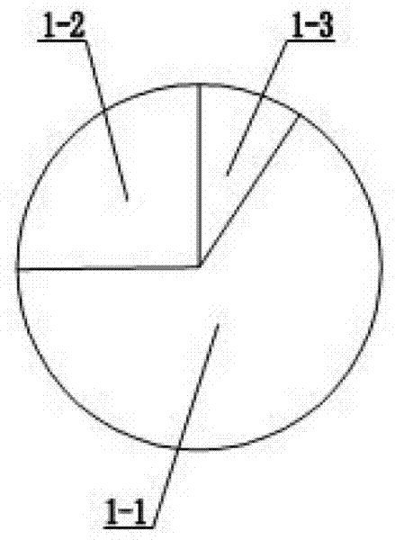
[0023] refer to figure 2 As shown, the first-stage dehumidification wheel 1 includes a dehumidification zone 1-1, a regeneration zone 1-2 and a pretreatment zone 1-3. The pretreatment zone 1-3 is located between the first-stage dehumidification rotor 1 turning from the regeneration zone 1-2 to the dehumidification zone 1-1, and is used to remove the residual high-temperature and high-humidity air during the regeneration process. The regeneration area 1-2 of the first-stage dehumidification rotor 1 accounts for 1 / 4 of the...


PUM


Abstract

The invention discloses a marine two-stage rotating-wheel dehumidifying air-conditioning system and an operating method thereof. The marine two-stage rotating-wheel dehumidifying air-conditioning system comprises a dehumidifying rotating wheel, a first-stage intercooler, a second-stage intercooler, a compression-type air-conditioner set, a humidifier, a processing fan and a regenerating fan whichare together connected in series. The adopted dehumidifying rotating wheel comprises a dehumidifying area, a regenerating area and a preprocessing area, and the preprocessing area is positioned between the regenerating area and the dehumidifying area of the dehumidifying rotating wheel. The waste heat of a ship is utilized as a heat source in the regenerating process of the dehumidifying rotatingwheel, and a waste-heat heater or a waste-gas heat-exchanging rotating wheel is adopted to heat regenerative air; and the dehumidified processed air is preliminarily cooled by utilizing seawater witha lower temperature. Because the preprocessing area is additionally arranged in the dehumidifying rotating wheel, the high-temperature high-humidity air remaining in the regenerating process of a dryer can be blown out of a rotating-wheel air passage at the preprocessing area, and the marine two-stage rotating-wheel dehumidifying air-conditioning system is favorable to the proceeding of the dehumidifying process at the dehumidifying area.

Description

technical field [0001] The invention relates to marine equipment, in particular to a marine two-stage dehumidification and air-conditioning system with two dehumidification runners using ship waste heat as a regenerative heat source and an operating method thereof. Background technique [0002] The thermal efficiency of marine diesel engines is only about 50%, and the rest of the heat is discharged into seawater or the atmosphere through cooling media, exhaust and heat dissipation. A large amount of waste heat on ships is discharged outdoors, causing a large waste of energy and also causing great pollution to the marine environment. Moreover, the dehumidification capacity of air conditioners in ships in summer is very large; at present, the air conditioning systems of ships basically use compression air conditioners for refrigeration, and use condensation dehumidification. Condensation dehumidification needs to reduce the surface temperature of the cooler to below the dew po...

Claims


Application Information

Patent Timeline
Patent Type & Authority Applications(China)
IPC IPC(8): F24F5/00F24F13/00F24F13/30
Inventor 陈武杨光海
Owner 海英荷普曼船舶设备(常熟)有限公司
Learn More