a solar collector

A technology of solar heat collectors and vacuum heat collector tubes, which is applied in the directions of solar heat collectors, solar thermal energy, and solar heat collectors using working fluids, etc., and can solve the problems of storage, packaging, transportation, installation, maintenance The commercialization of solar water heaters is low, and it is impossible to solve the problems of axial deformation of connecting pipelines, which is conducive to popularization and application, improving operability, and reducing axial deformation.

Inactive Publication Date: 2011-12-21
马志贵
View PDF4 Cites 6 Cited by
  • Summary
  • Abstract
  • Description
  • Claims
  • Application Information

AI Technical Summary

Problems solved by technology

However, due to the large difference in the coefficient of linear expansion between the metal inner tube and the glass outer tube, and the integral connection between the two adjacent ends of the metal inner tube is welded with a connecting pipe, the existing structure cannot eliminate the The stress changes brought about by this method cannot solve the technical problems such as the axial deformation of the connecting pipeline; and because most of the metal inner tubes are welded with heat-absorbing fins on the outer wall, and the plane formed by the heat-absorbing fins needs to be in line with the sun’s rays during installation. At the same time, because the pipe connection of the metal inner pipe of the heat collector is integrally connected, there are still problems in storage, packaging, transportation, installation, and maintenance. many inconveniences
In summary, the various pressurized solar water heaters of the prior art cannot be properly solved due to the above-mentioned problems, which is not conducive to its popularization and application.
So far, most of the non-pressurized solar water heaters are still on the market; the commercialization of pressurized solar water heaters is relatively low

Method used


Image

  • a solar collector
  • a solar collector
  • a solar collector

Examples


Embodiment Construction

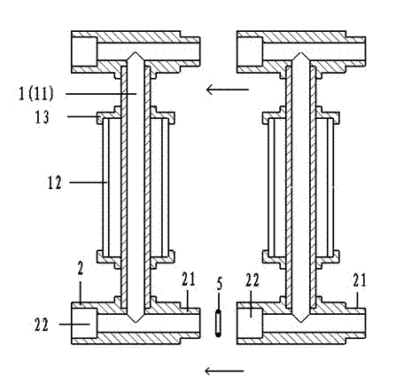
[0022] Such as figure 1 as shown,

[0023] On the bracket (not shown in the figure), there is a group of vacuum heat collecting tubes 1 arranged side by side. The end cap 13 constitutes. A special tee joint 2 is arranged between the two pipe ends of the metal inner pipe, and one end of the two axial ends of the special tee joint is provided with a shaft shoulder 21, and the other end is provided with a shaft hole 22; The pipe ends are welded, two-to-two special tee joints, the shaft shoulder and the shaft hole are plugged in, and the joint is sealed with a sealing ring 3. In this way, a group of metal inner pipes and the inner pipes of special three-way joints connected in series constitute the inlet and outlet water flow channels of the heat collector in a split type.

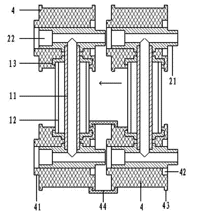
[0024] Such as figure 2 as shown,

[0025] The airtight end cap 13 between each metal inner pipe 11 and the glass outer pipe 12, and the metal inner pipe exposed outside the airtight end cap, and the pla...


PUM


Abstract

The present invention proposes a solar heat collector, the heat collector adopts a straight-through heat collecting tube as a basic component, and a special joint with a shaft shoulder and a shaft hole is arranged between the metal inner tube and the water flow channel of the heat collector. . For one or more sets of vacuum heat collecting tubes arranged side by side, the special joint can form the inlet and outlet water flow channels of the heat collector in a split type. On the basis of pressure bearing and high heat collection efficiency, the present invention uses a special joint to connect the heat collector pipes in separate parts, which better solves the stress change and axial heat loss of the existing pressure-bearing solar heat collector due to temperature changes. The problem of deformation, and realize the simplification of collector production, storage, packaging and transportation, installation, repair and maintenance, save labor and time, reduce product cost and prolong the service life of collector; it will be more conducive to bearing Popularization and application of pressure solar water heaters.

Description

technical field [0001] The invention relates to solar water heater technology, in particular to a heat collector of the solar water heater. Background technique [0002] Solar water heaters are widely used because of taking clean and inexhaustible solar energy. In order to improve the thermal efficiency and suitability of solar water heaters, various researches have been done on solar collectors. So far, solar collectors can be classified into two categories: non-pressure-bearing and pressure-bearing according to the pressure. The difference between the pressure-bearing type and the non-pressure-bearing type is that the latter does not need to consider issues such as the height difference between the installation position of the solar collector and the water tank and the water outlet. Since the pressurized solar water heater is an integral closed-circuit self-circulation system, the outlet water pressure and flow are stable, and it is more suitable for people's application...

Claims


Application Information

Patent Timeline
Patent Type & Authority Applications(China)
IPC IPC(8): F24J2/24F24J2/46F24S10/70
CPCY02E10/44
Inventor 马志贵马烈
Owner 马志贵
Why Eureka
Try Eureka