A ground test method for star sensor

A star sensor and ground testing technology, applied in the field of space science, can solve the problems of inability to assess the optical system, inability to test the polarity of the sensor, inability to test the accuracy of the star sensor, etc., and achieve the effect of simple testing

Active Publication Date: 2011-12-21
HARBIN INST OF TECH
View PDF3 Cites 25 Cited by
  • Summary
  • Abstract
  • Description
  • Claims
  • Application Information

AI Technical Summary

Problems solved by technology

However, this method can only test the electrical interface, circuit function and algorithm function of the star sensor. Since the electric star simulator directly outputs the star image coordinates to the star sensor, it cannot test the optical system, nor can it test the polarity of the sensor. sex
[0004] The polarity test of the ground-to-star sensor is: dock the static star simulator with the star sensor so that the optical axis of the static star simulator is parallel to the optical axis of the star sensor, and the star sensor is opposite to the static star simulator. Simulate the star map to observe and output attitude data, and judge whether the output polarity of the star sensor is correct by comparing the attitude output by the star sensor with the inertial attitude corresponding to the simulated star map; rotate the star sensor so that it is in line with the static star The simulator forms an appropriate angle. The star sensor observes the simulated star map generated by the static star simulator and outputs attitude data. By comparing the actual change trend and the theoretical change trend of the star sensor output attitude before and after rotation, the star sensor can be judged. Whether the output polarity is correct, but this method cannot test the accuracy of the star sensor
Therefore, the above methods can only test part of the functions of the star sensor, which has great limitations.

Method used


Image

  • A ground test method for star sensor
  • A ground test method for star sensor
  • A ground test method for star sensor

Examples


Embodiment 1

[0036] Example 1: Combining Figure 4 , the ground test method of a kind of star sensor of the present invention, the steps are as follows:

[0037] Step 1: Place the star sensor in a sky area suitable for stargazing;

[0038] Step 2: Use the theodolite to adjust the star sensor so that the Z axis of the star sensor points to the true north and the Y axis vertically faces the zenith;

[0039] Step 3: Connect the star sensor power supply and communication interface, and turn on the star sensor power supply;

[0040] Step 4: Receive the quaternion of the star sensor in the inertial coordinate system;

[0041] Step 5: Read the local time;

[0042] Step 6: According to the local time, transfer the attitude of the star sensor to the quaternion in the WGS84 coordinate system;

[0043] Step 7: Read the local longitude and latitude;

[0044] Step 8: Convert the quaternion in the WGS84 coordinate system of the star sensor into three-axis Euler angles;

[0045] Step 9: Calculate t...

Embodiment 2

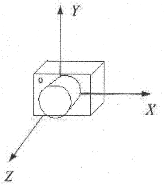
[0055] Example 2: Combining figure 2 ,, image 3 , define the star sensor image space coordinate system as (such as figure 2 ): The origin O is located at the center of the star sensor sensor (CCD), facing the star sensor lens, the X axis is parallel to the CCD plane to the right, the Y axis is parallel to the CCD plane upward, and the Z axis is vertical to the CCD face outward. That is to say, the polarity of the star sensor is (such as image 3 ):

[0056] Suppose the attitude angle of the star sensor rotating around the X axis is called the yaw angle, the attitude angle around the Y axis is called the pitch angle, and the attitude angle around the Z axis is called the roll angle.

[0057] The star sensor output attitude is the relationship between the star sensor image space coordinate system and the earth center inertial coordinate system (ie J2000.0 coordinate system), that is to say, the yaw angle output by the star sensor and the direction the optical axis The dec...

Embodiment 3

[0080] Example 3: Binding Figure 5-Figure 8 , Star sensor main performance indicators: field of view: 12 ° × 9 °; area array: 670 × 520; detection magnitude: 6Mv; data update rate: 8Hz.

[0081] Select a certain type of star sensor and a certain type of manual three-axis turntable. Before the experiment, use high-precision GPS to measure the local longitude of 121.10481° east longitude and 31.15025° north latitude, and install the star sensor on the manual turntable. , adjust the turntable so that the Z-axis of the star sensor points to true north, and the Y-axis vertically faces the zenith. Turn on the star sensor, the host computer receives the attitude quaternion of the star sensor in the J2000.0 coordinate system and the time of shooting the image, and the host computer software calculates the attitude of the star sensor in the J2000.0 coordinate system according to the time of shooting the image Convert the quaternion to the quaternion in the WGS84 coordinate system, an...


PUM


Abstract

The invention provides a ground testing method of a star sensor. The method comprises the following steps of: adjusting the star sensor by using a theodolite so that the Z axis of the star sensor points to true north and the Y axis of the star sensor vertically faces towards zenith; receiving a quaternion of the star sensor under an inertial coordinate system; converting the posture of the star sensor into a quaternion under a WGS84 coordinate system; converting the quaternion under the WGS84 coordinate system of the star sensor into a three-axis Euler angle; continuously operating the star sensor for 30 minutes, storing the difference between a roll angle and the local longitude and the difference between a drift angle and the local latitude in real time, and counting precisions of the roll angle and the drift angle; and storing the difference between a pitch angle and the local longitude in real time, and counting the precision of the pitch angle. According to the method disclosed by the invention, the testing process is simple; any special equipment is unnecessary; the method is not only used for testing the precision of the three-axis Euler angle of the star sensor but also used for completely testing the three-axis polarity of the star sensor; and in addition, only when the time precision satisfies requirements, the method is also used for testing the absolute longitude of the star sensor.

Description

(1) Technical field [0001] The invention relates to space science, in particular to a ground testing method for a star sensor. (2) Background technology [0002] A star sensor is an optical attitude sensor that senses a star's radiation and measures the satellite's orientation relative to that star. It takes the star as a reference object, uses the star map actually captured, and through a series of calculations, determines the instantaneous pointing of the star sensor optical axis in the inertial space, thereby determining the attitude of the aircraft. Since the opening angle of stars is very small and the direction of starlight in the inertial coordinate system is known precisely, the star sensor has high measurement accuracy, and it is the attitude measurement sensor with the highest measurement accuracy in the current navigation system. Before the star sensor is put into use, a series of ground function tests must be carried out to verify the effectiveness and reliabili...

Claims


Application Information

Patent Timeline
Patent Type & Authority Applications(China)
IPC IPC(8): G01C25/00
Inventor 李葆华陈希军奚伯齐温奇咏
Owner HARBIN INST OF TECH
Why Eureka
Try Eureka