A molding die for rod-shaped insulator pillars for high-speed railways

A technology for high-speed railways and forming molds, applied in the direction of insulators, supporting insulators, circuits, etc., can solve the problems of prolonging processing hours, excessive scrapping, shrinkage cavities, etc., and achieve the effects of saving materials, avoiding turning processing, and improving molding efficiency

Active Publication Date: 2011-12-21
RUGAO DASHENG LINE EQUIP
View PDF4 Cites 11 Cited by
  • Summary
  • Abstract
  • Description
  • Claims
  • Application Information

AI Technical Summary

Problems solved by technology

[0003] At present, there are two ways to produce this kind of rod-shaped insulator pillars for high-speed railways: one is the method of casting, and its disadvantages are: the internal structure is loose, there are defects such as shrinkage cavities, cracks, etc., the quality cannot meet the requirements, and there are many defects. Big safety hazard, and more scrapped
[0004] The forging method can also be used. Due to the shape and mold, the general high-speed railway rod-shaped insulator pillar mold needs to forge the large crimping part first, and then forge the prototype structure of the small crimping part. Machining is required, and it cannot be formed at one time, which prolongs the processing time, and requires a lot of materials, high production costs, and does not have market competitiveness

Method used


Image

  • A molding die for rod-shaped insulator pillars for high-speed railways
  • A molding die for rod-shaped insulator pillars for high-speed railways
  • A molding die for rod-shaped insulator pillars for high-speed railways

Examples


Embodiment Construction

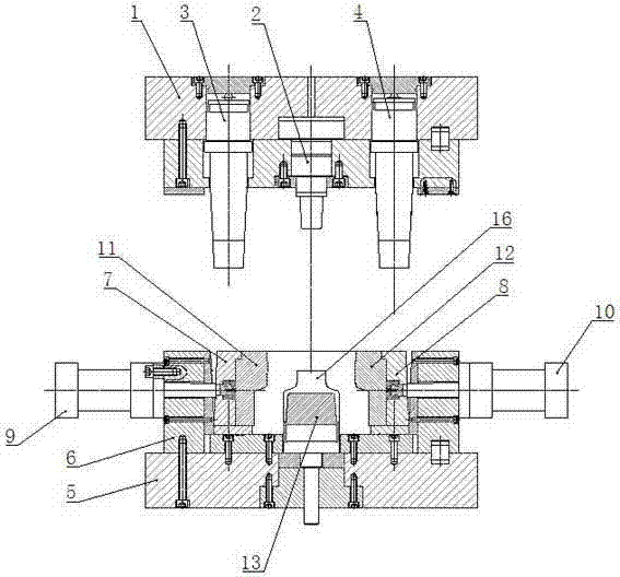
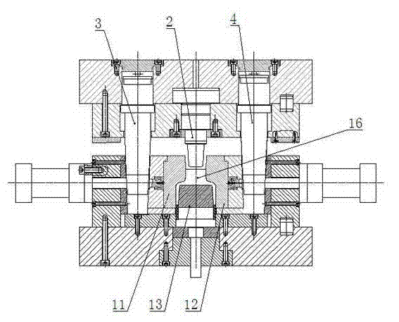
[0014] like figure 2 As shown, it includes upper template 1, upper punch 2, left die locking cylinder 3, right die locking cylinder 4, lower template 5, die base 6, left die 7, right die 8, left cylinder 9. Right cylinder 10.

[0015] The upper punch 2 is installed in the center of the above-mentioned upper template 1, and the vertical left die locking cylinder 3 and the right die locking cylinder 4 are respectively installed on both sides. The piston rod ends of the two die locking cylinders 3 and 4 The top is conical or wedge-shaped.

[0016] Die holder 6 is installed on the lower template 5, left die 7, right die 8 are arranged in the die holder 6, left side cylinder 9 and right side cylinder 9 are installed on the outside die holder 6 of left die 7 and right die 8 Cylinder 10, the cylinder body of left side cylinder 9, right side cylinder 10 is connected and fixed with die base 6, and piston rod is connected with left die 7 and right die 8 respectively.

[0017] The le...


PUM


Abstract

The invention relates to a bar-shaped insulator support post molding die for a high-speed railway. The bar-shaped insulator support post molding die comprises an upper template and a lower template, wherein an upper punching head is arranged in the center of the upper template; a left vertical female die locking cylinder and a right vertical female die locking cylinder are arranged on both sides of the upper template respectively; a die seat is arranged on the lower template; a left female die and a right female die are arranged in the die seat, and are driven to move horizontally by a left side cylinder and a right side cylinder respectively; the end parts of piston rods of the left female die locking cylinder and the right female die locking cylinder have conical or wedged structures; and the outer side faces of the left female die and the right female die are provided with conical or wedged structures which are matched with the piston rods of the left female die locking cylinder and the right female die locking cylinder respectively. After the left side cylinder and the right side cylinder are used for driving die assembly of a left die kernel and a right die kernel, and the left female die locking cylinder, the right female die locking cylinder and the upper punching head descend quickly, the piston rods of the two female die locking cylinders are embedded into gaps between the left and right female dies and the die seat, and the piston rods are matched with the conical or wedged structures of the left and right female dies to drive the left and right die kernels to belocked, so that one-step molding of a small compression joint part is realized, the molding efficiency is improved, turning is avoided, and materials are saved.

Description

technical field [0001] The invention relates to a mold, in particular to a molding mold for rod-shaped insulator pillars used in high-speed railways. Background technique [0002] Rod-shaped insulator posts for high-speed railways are used for high-speed railway catenary wrist support, such as figure 1 As shown, it is composed of a large crimping part 14 and a small crimping part 15, the large crimping part 14 is in the shape of a rotating body tube, and the small crimping part 15 is in the shape of a non-rotating body tube, and the outer surface of the small crimping part The middle is sunken inwards. [0003] At present, there are two ways to produce this kind of rod-shaped insulator pillars for high-speed railways: one is the method of casting, and its disadvantages are: the internal structure is loose, there are defects such as shrinkage cavities, cracks, etc., the quality cannot meet the requirements, and there are many defects. Big safety hazard, and scrap more. ...

Claims


Application Information

Patent Timeline
Patent Type & Authority Applications(China)
IPC IPC(8): H01B19/00H01B17/14
Inventor 征大生刘松明
Owner RUGAO DASHENG LINE EQUIP
Why Eureka
Try Eureka