Transverse Flux Multiphase Reluctance Motor

一种磁阻电机、横向磁通的技术,应用在磁路、同步机、电动组件等方向,能够解决影响电流控制精度等问题

Active Publication Date: 2011-12-21
HARBIN INST OF TECH
View PDF4 Cites 9 Cited by
  • Summary
  • Abstract
  • Description
  • Claims
  • Application Information

AI Technical Summary

Problems solved by technology

[0003] In order to solve the problem that there is magnetic coupling between the phases existing in the traditional multi-phase permanent magnet synchronous motor, which affects the control accuracy of the current, the present invention proposes a transverse flux multi-phase reluctance motor

Method used


Image

  • Transverse Flux Multiphase Reluctance Motor
  • Transverse Flux Multiphase Reluctance Motor
  • Transverse Flux Multiphase Reluctance Motor

Examples


specific Embodiment approach 1

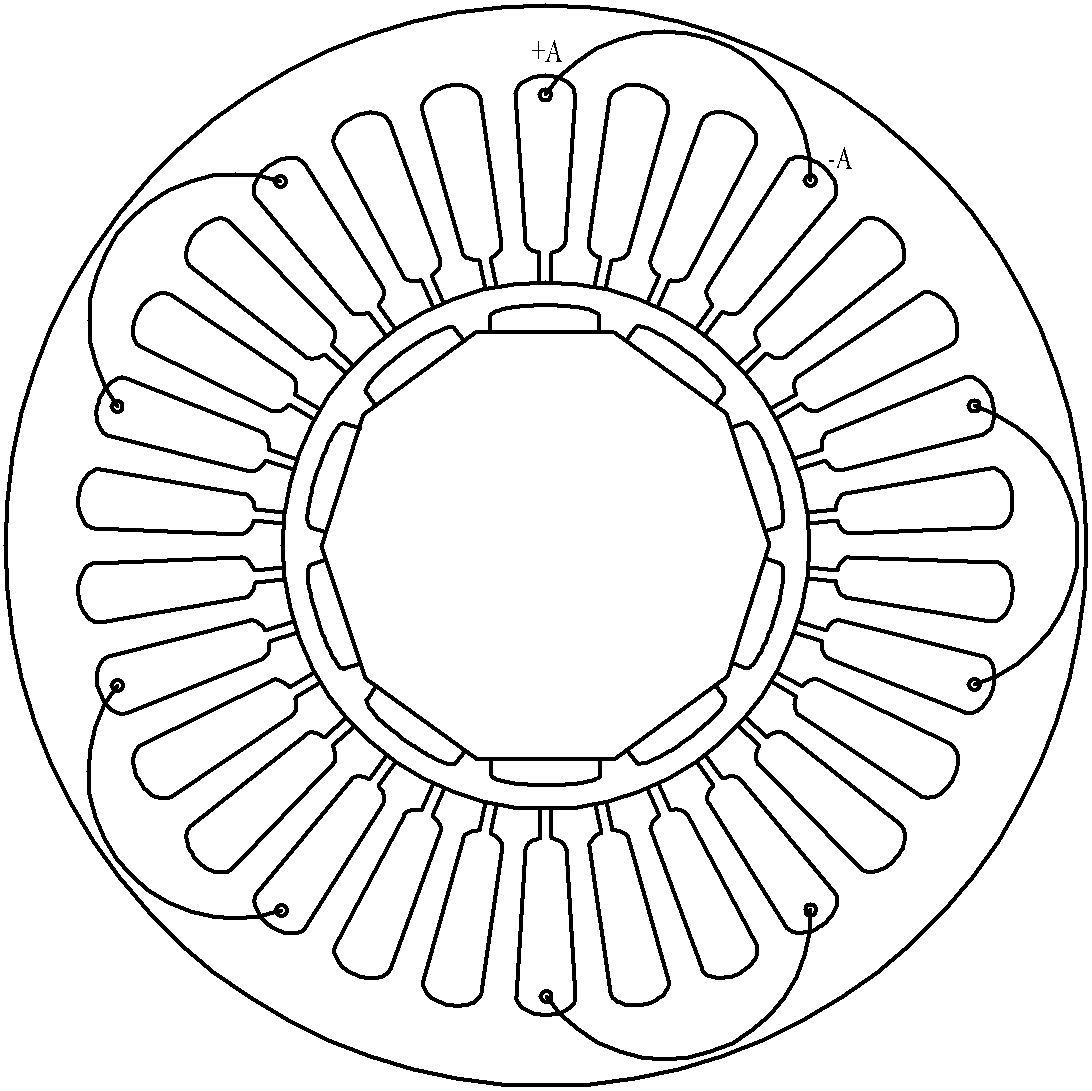
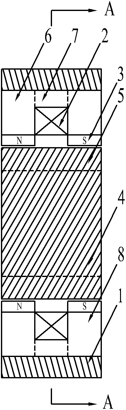
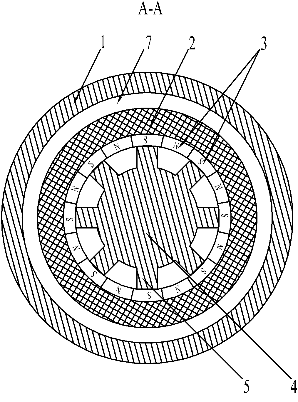
[0094] Specific implementation mode one: combine figure 2 , image 3 , Figure 4 Describe this embodiment, the transverse flux multiphase reluctance motor described in this embodiment is characterized in that it is composed of a stator and a rotor; an air gap is left between the stator and the rotor;

[0095] The rotor is composed of a rotor frame 4 and a plurality of rotor teeth 5; the plurality of rotor teeth 5 are evenly arranged on the outer circumferential surface of the rotor frame 4; the rotor frame 4 and the rotor teeth 5 are of an integrated structure;

[0096] The stator is composed of a casing 1 and m phase armature units, m is the phase number of the reluctance motor, m≥3;

[0097] The casing 1 adopts a cylindrical casing; the m phase armature units are sequentially arranged in the casing 1 along the axial direction, and each phase armature unit is sequentially staggered by 360° / m electrical angle along the circumferential direction ;

[0098]Each phase armatu...

specific Embodiment approach 2

[0107] Specific implementation mode two: combination Figure 5 to Figure 7 Describe this embodiment, the transverse flux multiphase reluctance motor described in this embodiment is composed of a stator and a rotor; an air gap is left between the stator and the rotor;

[0108] The rotor is composed of a rotor frame 4 and a plurality of rotor teeth 5; the plurality of rotor teeth 5 are evenly arranged on the outer circumferential surface of the rotor frame 4; the rotor frame 4 and the rotor teeth 5 are of an integrated structure;

[0109] The stator is composed of a casing 1 and m phase armature units, m is the phase number of the reluctance motor, m≥3;

[0110] The casing 1 adopts a cylindrical casing; the m phase armature units are sequentially arranged in the casing 1 along the axial direction, and each phase armature unit is sequentially staggered by 360° / m electrical angle along the circumferential direction ;

[0111] Each phase armature unit is composed of a unit armatu...

specific Embodiment approach 3

[0123] Specific implementation mode three: combination Figure 8 to Figure 10 Describe this embodiment, the transverse flux multiphase reluctance motor described in this embodiment is composed of a stator and a rotor; an air gap is left between the stator and the rotor;

[0124] The rotor is composed of a rotor frame 4 and a plurality of rotor teeth 5; the plurality of rotor teeth 5 are evenly arranged on the outer circumferential surface of the rotor frame 4; the rotor frame 4 and the rotor teeth 5 are of an integrated structure;

[0125] The stator is composed of a casing 1 and m phase armature units, m is the phase number of the reluctance motor, m≥3;

[0126] The casing 1 adopts a cylindrical casing; the m phase armature units are sequentially arranged in the casing 1 along the axial direction, and each phase armature unit is sequentially staggered by 360° / m electrical angle along the circumferential direction ;

[0127] Each phase armature unit is composed of a unit arm...


PUM


Abstract

The invention discloses a transverse magnetic flux multi-phase reluctance motor, and relates to a reluctance motor, which solves the problem that magnetic coupling is existed between phases in a traditional multi-phase permanent magnet synchronous motor to affect the control precision of current. The reluctance motor consists of a stator and a rotor, wherein m phase armature units are arranged inan enclosure along an axial direction in sequence, and each phase armature unit is staggered in a 360 DEG / m electrical angle along a circumference direction in sequence; an armature coil is embedded in an annular space formed among first to third circular iron core sections; permanent magnets are fixedly arranged on the internal surfaces of the first and the third circular iron core sections along the circumference direction with alternated N-pole and S-pole in sequence; and a pole distance taum between every adjacent two permanent magnets and a tooth space taup of rotor teeth arranged along the circumference direction satisfy the formula of 2taum=taup. The reluctance motor disclosed by the invention eliminates the alternating mutual inductance, improves control accuracies of motor current and electromagnetic torque and dynamic property of ta system; and improves the reliability and the safety of the motor since the permanent magnets are located above the stator.

Description

technical field [0001] The invention relates to a reluctance motor, in particular to a multi-phase reluctance motor. Background technique [0002] The structure of the traditional multi-phase permanent magnet synchronous motor, such as figure 1 As shown; the armature winding of the motor is a distributed winding, the number of coils required to form the winding is large, the winding ends of each phase of the winding cross each other, the winding ends are long, and the copper consumption is large; the winding insulation is complicated and the manufacturing cost is high. Since there is magnetic coupling between phases, on the one hand, the existence of mutual inductance will affect the control accuracy of the current; The power consumption is large, which limits the further improvement of the motor efficiency. At the same time, since the permanent magnet is located on the rotor, the structural strength and allowable temperature rise of the rotor are limited, which restricts ...

Claims


Application Information

Patent Timeline
Patent Type & Authority Applications(China)
IPC IPC(8): H02K21/00H02K1/24H02K1/17
CPCH02K2201/12H02K21/00H02K21/44H02K1/24H02K1/17
Inventor 寇宝泉谢大纲吴太箭周一恒
Owner HARBIN INST OF TECH
Why Eureka
Try Eureka