

A centering clamping device for crystal material processing
A crystal material and clamping device technology, applied in stone processing equipment, work accessories, manufacturing tools, etc., can solve the problems affecting the processing quality of silicon cores, small contact surface, easy to break, etc., to improve production efficiency and grinding quality , improve work efficiency, and achieve uniform grinding effect
- Summary
- Abstract
- Description
- Claims
- Application Information
AI Technical Summary
Problems solved by technology
Method used
Image

Examples
Embodiment Construction
[0026] The present invention can be explained in more detail with reference to the following examples, but the present invention is not limited to the combination of these examples.
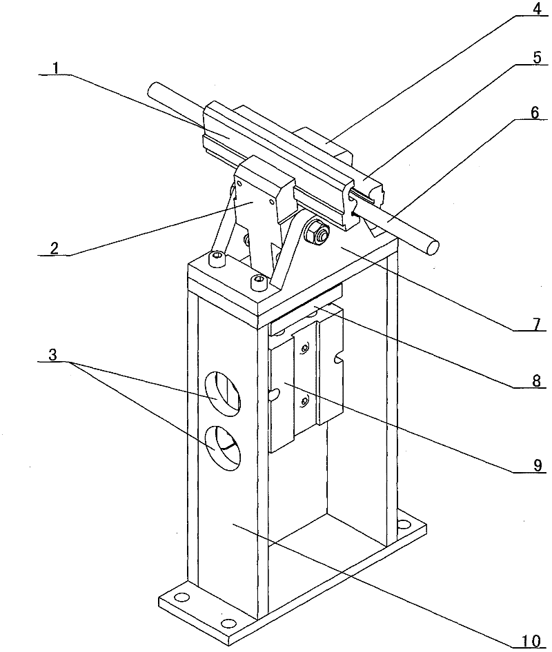
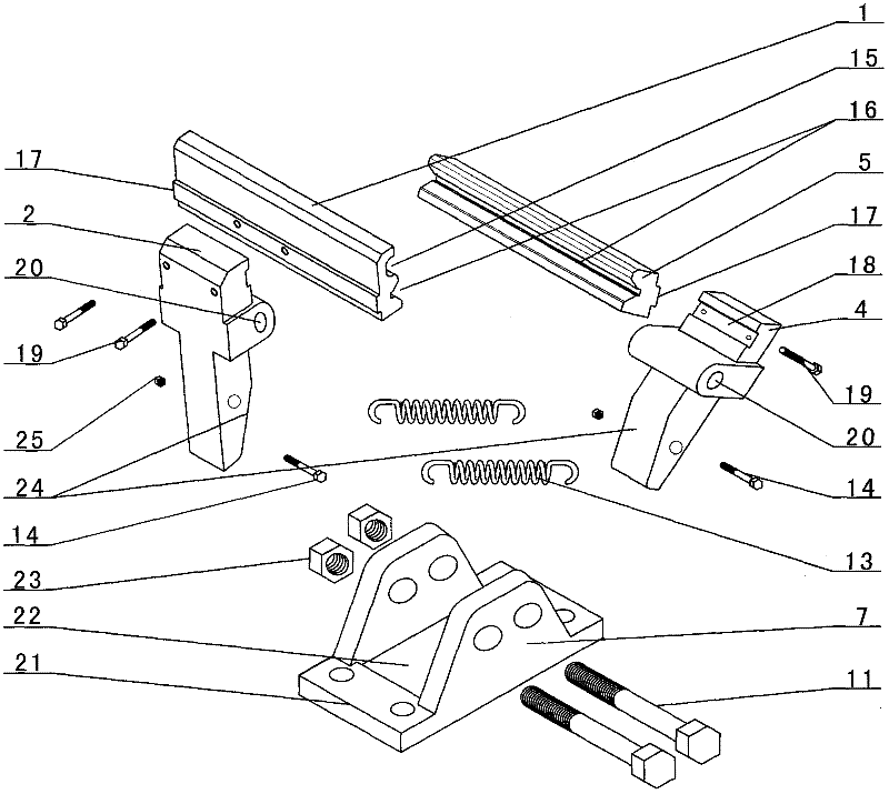
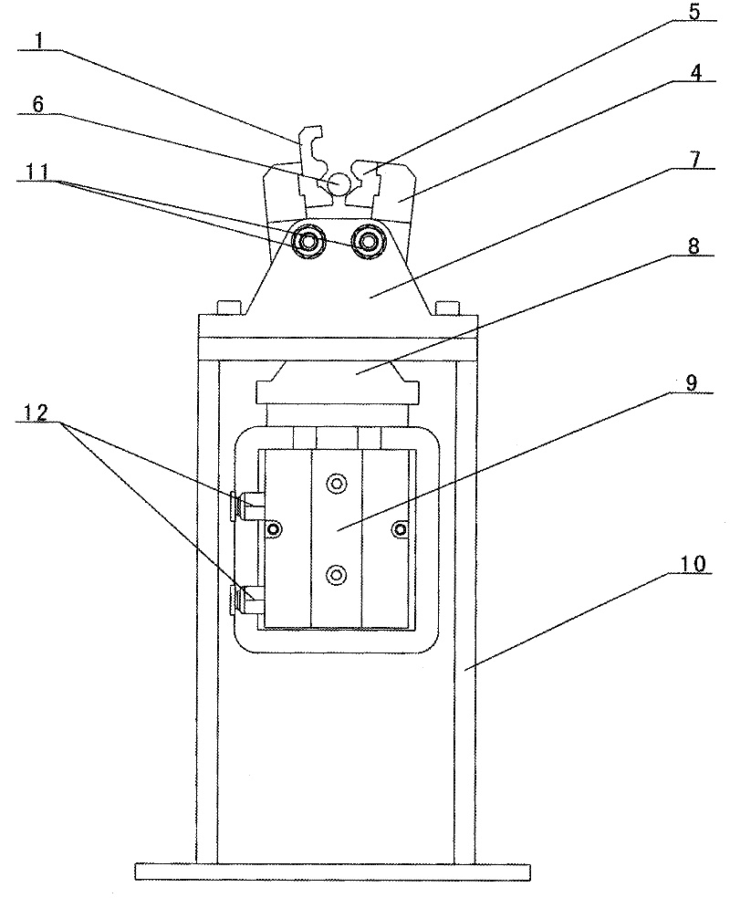
[0027] combined with Figure 1~6 The centering clamping device for crystal material processing described in includes a clamping mechanism for fixing the silicon core 6; an automatic return mechanism for the clamping mechanism; a base for placing the clamping mechanism; The wedge block 8 and the power mechanism of the clamping mechanism; the clamping mechanism for fixing the silicon core 6 includes a side rocker 2, a large clamping block 1, the other side rocker 4, and a small clamping block 5. The upper opposite surfaces of the rocker arm 2 on one side and the rocker arm 4 on the other side are respectively fixedly connected to the outer surfaces of the large clamping block 1 and the small clamping block 5, and on the opposite surfaces of the large clamping block 1 and the small clamping block 5 ...
PUM
 Abstract
Description
Claims
Application Information