
Computerized flat knitting machine press wheel assembly

A computerized flat knitting knitting machine and cloth pressing wheel technology, applied in knitting, weft knitting, textile and paper making, etc., can solve the problems of uneven force, large fabric pressure, inability to adjust the fabric pressure, etc. The effect of the coefficient of friction

Inactive Publication Date: 2011-12-28
NINGBO CIXING
View PDF7 Cites 5 Cited by
  • Summary
  • Abstract
  • Description
  • Claims
  • Application Information

AI Technical Summary

Problems solved by technology

[0003] Existing computerized flat knitting machines all use an integrated cylindrical press wheel. The friction coefficient of the outer surface of this press wheel is small, and a large pressure is required to provide sufficient friction for the fabric. The computerized flat knitting machine must use the corresponding type of pressing wheel, and the pressing wheels of different sizes and types of computerized flat knitting machines cannot be used with each other at all, which increases the production cost of computerized flat knitting machine producers
[0004] Since the cloth pressing wheel is a long whole, in the existing mode, once the cloth pressing wheel in use is partially damaged, the entire pressing cloth wheel must be replaced, and because the longer cloth pressing wheel is often stressed during use It is not uniform, and the pressure wheel will bend and break after working for a period of time, which greatly increases the cost of the user
[0005] In addition, the existing press rollers cannot adjust the pressure on the fabric, and the same pressure is used in different situations, so that some fabrics cannot be effectively pulled, while other fabrics are damaged due to excessive pressure

Method used


Image

  • Computerized flat knitting machine press wheel assembly
  • Computerized flat knitting machine press wheel assembly
  • Computerized flat knitting machine press wheel assembly

Examples


Embodiment Construction

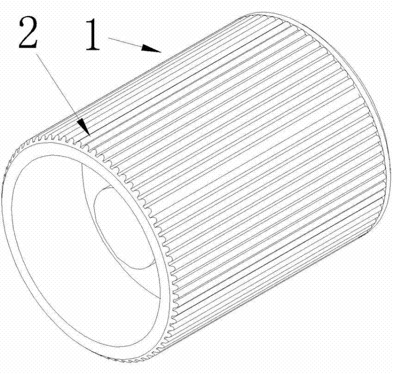
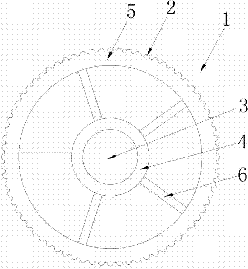
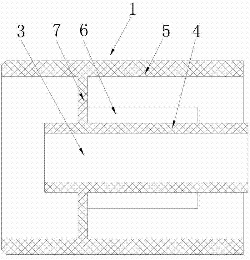
[0023] see figure 1 , figure 2 and image 3 , the press wheel 1 is cylindrical, the axial length is 25% larger than the diameter, and its outer surface has uniformly distributed axial friction ribs 2. These friction ribs 2 can increase the friction coefficient of the outer surface of the press wheel 1. Provides enough friction to the fabric with light pressure. The shaft hole 3 is shorter than the cloth pressing wheel 1, and the shaft hole 3 and the surface of the cloth pressing wheel 1 are hollowed out to form the shaft hole wall 4 and the outer wall 5, which can effectively reduce the cloth pressing without affecting the useful size and shape. Wheel 1 weight. One end of the shaft hole wall 4 protrudes outside the cloth pressing wheel 1, and the other end of the shaft hole wall 4 is in the cloth pressing wheel 1 because the length of the shaft hole 3 is less than the length of the cloth pressing wheel 1. There are five supporting ribs 6 between the shaft hole wall 4 and ...


PUM


Abstract

The invention discloses a cloth pressing wheel assembly of a computerized flat knitting machine, which comprises a cloth pressing wheel and a cloth pressing wheel seat. The cloth pressing wheel is cylindrical and has a shaft hole inside; a cloth pressing wheel shaft seat is movably connected to the cloth pressing wheel seat , a cloth pressing wheel shaft is fixed on both sides of the cloth pressing wheel shaft seat, and the two cloth pressing wheels are respectively installed on the cloth pressing wheel shaft through the shaft holes; there is also a pressure adjusting screw seat and a pressure adjusting screw thread on the cloth pressing wheel seat It is connected to the pressure regulating screw rod seat, and the lower end of the pressure regulating screw rod is connected with the press wheel shaft seat. The press wheel assembly of the computerized flat knitting machine of the present invention can use different numbers of individuals to freely combine to form pulling devices of various lengths, and can provide greater friction under the same pressure, and can freely adjust the press wheel to the fabric The pressure can be adjusted to adjust the friction force, and it can also reduce the difficulty and cost of maintenance when the pulling device is damaged.

Description

technical field [0001] The invention belongs to the technical field of knitting machines, in particular to a press wheel assembly of a computerized flat knitting machine. Background technique [0002] The pressure wheel of the computerized flat knitting machine is mainly used to provide friction for the fabric, so that the fabric can be pulled down smoothly after being knitted. [0003] Existing computerized flat knitting machines all use an integrated cylindrical press wheel. The friction coefficient of the outer surface of this press wheel is small, and a large pressure is required to provide sufficient friction for the fabric. The computerized flat knitting machine must use the corresponding model of presser wheels, and the presser wheels of computerized flat knitting machines of different sizes and models cannot be used for each other at all, which increases the production cost of computerized flat knitting machine producers. [0004] Since the cloth pressing wheel is a...

Claims


Application Information

Patent Timeline
Patent Type & Authority Applications(China)
IPC IPC(8): D04B15/90
Inventor 孙平范
Owner NINGBO CIXING
Learn More