Plunger Type Pneumatic Quick Change Fitting

A plunger-type, air-outlet technology, used in mechanical equipment, couplings, etc., can solve the problems of short service life, many parts, and large material consumption, and achieve extended service life, improved service life, and safe and reliable operation. Effect

Inactive Publication Date: 2011-12-28
庄志军 +1
View PDF1 Cites 12 Cited by
  • Summary
  • Abstract
  • Description
  • Claims
  • Application Information

AI Technical Summary

Problems solved by technology

The pneumatic quick change joint of this structure consists of a female joint, an outer sealing ring, a check valve core, an inner sealing ring, a steel ball, a male joint, a guide sleeve, a Y-shaped sealing ring, a valve core spring, an outer casing spring, an outer casing and a locking The sleeve is composed of many parts and complex structure. It is difficult to process the sealing groove on the guide sleeve and the male joint, and it is difficult to assemble the three seals. Although there are many sealing links, there is no sealing structure between the inner hole of the female joint and the outer circle of the guide sleeve. The O seal ring installed at the front end is easily sheared and damaged during the left and right movement, resulting in unsatisfactory overall sealing effect and short service life. At the same time, the radial dimension is relatively large, which is difficult to meet the user's requirements for small-volume pneumatic quick-change joints. Requirements, the disassembly and assembly between the female joint and the locking sleeve is realized through the outer hexagon, which further increases the radial dimension of the part, making the geometric dimension of the part unable to be reduced, and the material consumption is large

Method used


Image

  • Plunger Type Pneumatic Quick Change Fitting
  • Plunger Type Pneumatic Quick Change Fitting
  • Plunger Type Pneumatic Quick Change Fitting

Examples


Embodiment 1

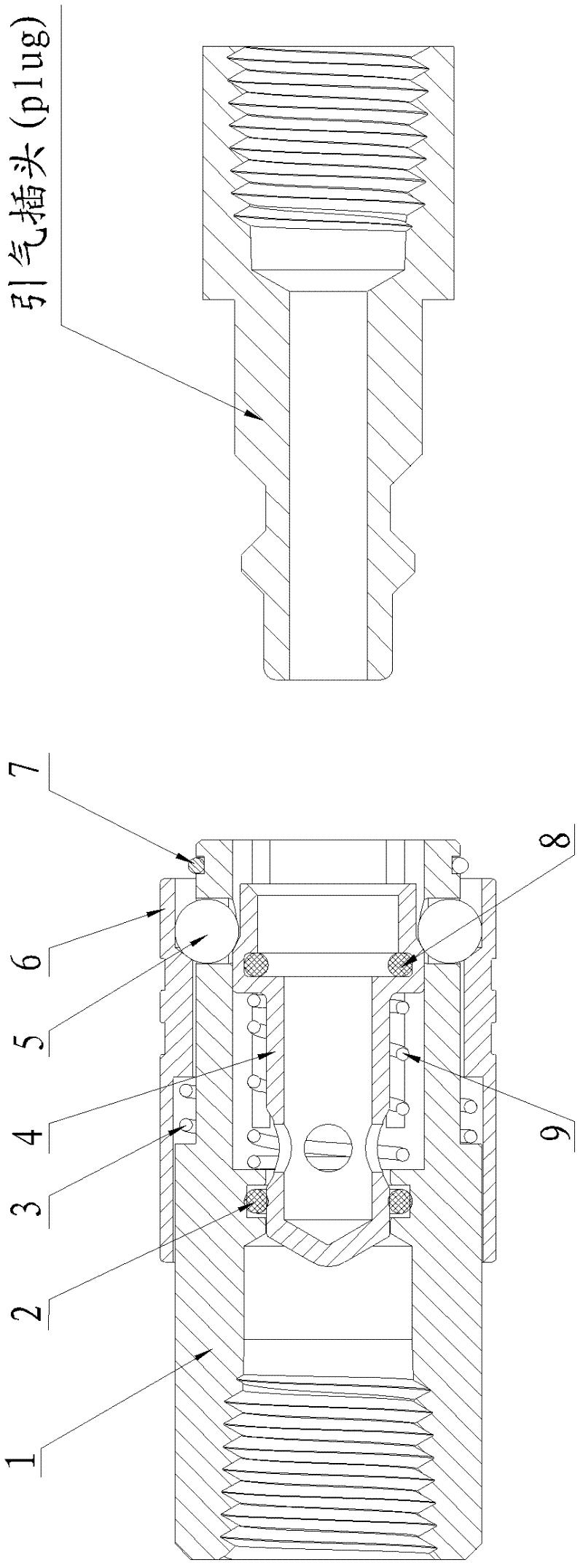
[0033] Embodiment 1: A kind of plunger type pneumatic quick-change joint, such as figure 1 As shown, it includes intake joint 1, intake sealing ring 2, sliding sleeve spring 3, valve core 4, locking steel ball 5, moving sliding sleeve 6, sliding sleeve limiter 7, air outlet sealing ring 8 and valve core Spring 9, the air inlet sleeve 1 is a casing structure, such as figure 2 , image 3 As shown, the left section is the connecting section, and the right section is the matching section. Four pressure relief grooves 13 are uniformly arranged in the circumferential direction on the inner hole wall of the matching section of the intake sleeve 1. The function of the pressure relief grooves 13 is When the air-inducing plug Plug is inserted, it produces a pressure relief effect, which is more conducive to the easy insertion of the air-inducing plug Plug. Four steel ball holes 14 are evenly arranged on the outer circle of the right end of the fitting section of the air-intake connector...

Embodiment 2

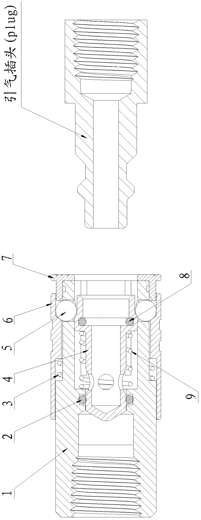
[0034] Embodiment 2: A kind of plunger type pneumatic quick-change joint, such as Figure 7 As shown, its structure is similar to that of Embodiment 1, the difference is that the sliding sleeve limiter 7 arranged between the moving sliding sleeve 6 and the intake joint 1 is changed from a shaft retaining ring to a step with a shaft shoulder Axle sleeve, in this example, the inner hole of the stepped sleeve is matched with the outer circle of the right end of the air intake sleeve 1, and the two are fixedly connected, and a protective step is provided at the right end of the stepped sleeve, and the outer diameter of the protective step is the same as The maximum external diameter of mobile sliding sleeve 6 right ends is identical. The function of the stepped sleeve can not only limit the axial position of the movable sliding sleeve 6, but also prevent the operator from directly touching the movable sliding sleeve 6 during the working process, so that the movable sliding sleeve ...

Embodiment 3

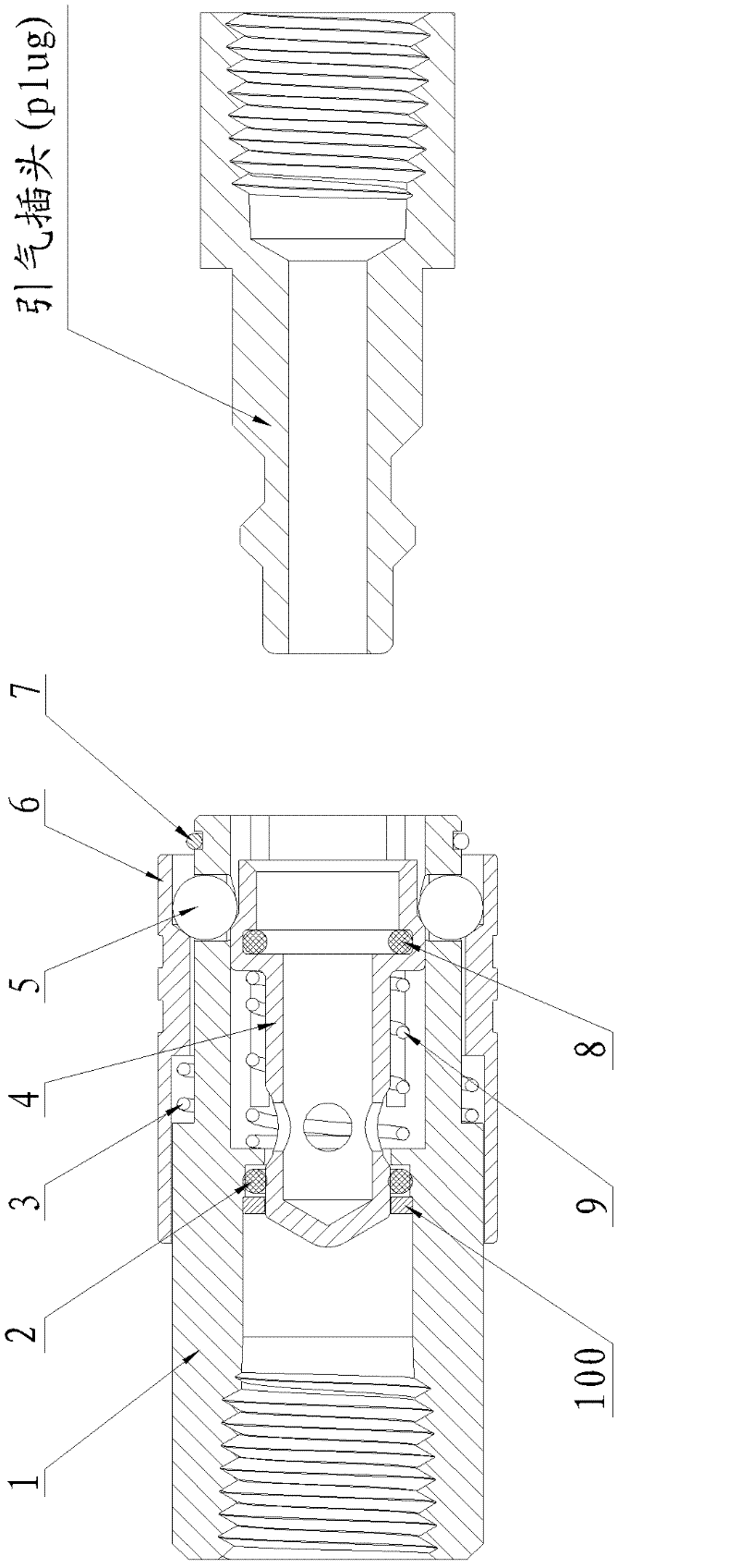
[0035] Embodiment 3, a kind of plunger type pneumatic quick-change joint, such as Figure 8 As shown, its structure is similar to that of Embodiment 1, the difference is: the installation structure of the air intake sealing ring 2, in this example, the air intake sealing ring 2 is installed on the left side of the front guide hole 11, and the left retaining ring 100 axial limit.


PUM


Abstract

A plunger-type pneumatic quick-change joint, including an air inlet sleeve, a sliding sleeve spring, an air inlet sealing ring, a valve core, a locking steel ball, a moving sliding sleeve, a sliding sleeve limiter, an air outlet sealing ring and a valve core spring, A pressure relief groove is provided on the inner hole wall of the rear guide hole of the air intake joint along the circumference, and a steel ball hole is provided on the outer circle at the right end of the matching section. The locking steel ball is placed in the steel ball hole, and the air intake joint, The axial sliding limit of the valve core is controlled by the locking steel ball between the valve core and the sliding sleeve. Before the bleed air plug is inserted, the locking steel ball is located in the locking cavity; The stroke groove can ensure the non-shearing contact between the outer circle and the intake sealing ring of the valve core during the opening and closing process, ensuring that the valve core can be closed, opened easily, and has a long service life. Compared with existing similar products, it has simple structure, small radial dimension, long service life, easy insertion of bleed air plug, small pressure loss, and safe and reliable operation.

Description

Technical field: [0001] The invention relates to a pneumatic quick-change joint, which is widely used for quick connection of gas delivery pipelines. Background technique: [0002] Pneumatic quick-change joints are an essential connection part for quick connection of gas pipelines. All industries that use compressed air need to use gas quick-connects. In Chinese patent CN101907210A (Patent No. ZL201010234636.4) discloses "a pneumatic quick joint, which includes a female joint connected to the air inlet pipe and a male joint connected to the air outlet pipe, and is fixedly installed at the air outlet end of the female joint. There is a locking sleeve, and a check valve core with an exhaust channel is installed in the inner hole of the female joint and the locking sleeve. The air inlet end of the male joint extends into the inner hole of the locking sleeve and is connected with the The exhaust passages are connected, and a guide sleeve is sandwiched between the locking sleeve...

Claims


Application Information

Patent Timeline
Patent Type & Authority Applications(China)
IPC IPC(8): F16L37/23F16L37/40
Inventor 庄志军华文明
Owner 庄志军
Why Eureka
Try Eureka