A multi-array adaptive capacitance tomography sensor device

A technology of capacitance tomography and sensor device, which is applied in the field of detection to achieve the effects of realizing measurement, increasing the intensity of measurement signals, and realizing radial resolution

Inactive Publication Date: 2011-12-28
BEIJING UNIV OF TECH
View PDF7 Cites 23 Cited by
  • Summary
  • Abstract
  • Description
  • Claims
  • Application Information

AI Technical Summary

Problems solved by technology

The driving protection structure can make the ECT sensor more accurate in cross-sectional imaging, and the terminal grounding protection structure can make the ECT sensor maintain high sensitivity in axial measurement. The traditional ECT sensor cannot be adjusted according to different measurement needs after the design is completed. Different sensor guard plate structures

Method used


Image

  • A multi-array adaptive capacitance tomography sensor device
  • A multi-array adaptive capacitance tomography sensor device
  • A multi-array adaptive capacitance tomography sensor device

Examples


Embodiment 1

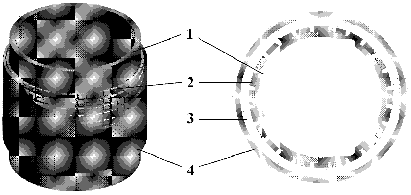
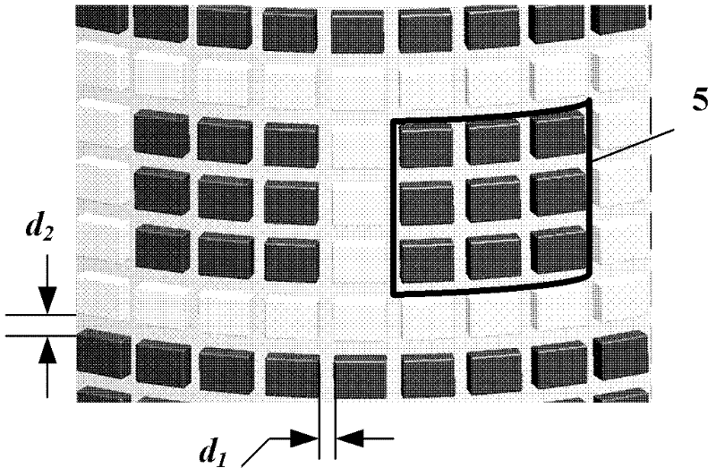
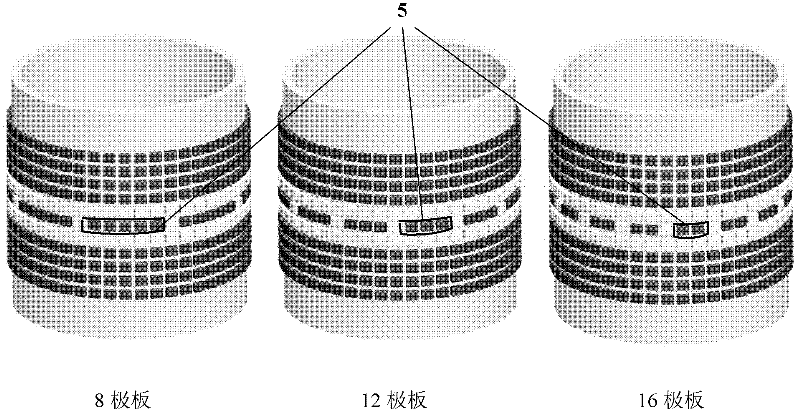
[0037] Example 1 see Figure 5 , Figure 5 It is a schematic diagram of the structure of the adaptive capacitance tomography sensor with 8 plates and driving protection mode. The setting sensor is composed of 11 ring-shaped plate groups, and each ring-shaped plate group is composed of 48 unit plates. The driving protection layer and the measurement layer are composed of 8 combined plates respectively. The combined plates of the driving protection layer are composed of 4 rows and 5 columns of unit plates, and each combined plate has a total of 20 unit plates. The combined plate of the measurement layer consists of 1 row and 5 columns of unit plates, and each combined plate has 5 unit plates. A non-conducting annular plate group is separated between the driving protection layer and the measuring layer, and a row of non-conducting unit plates is spaced between each adjacent combined plate.

[0038] The radius of the inner wall of the empty insulating container (1) is 50 mm, th...

Embodiment 2

[0039] Example 2 see Figure 7 , Figure 7 It is a schematic diagram of the structure of the self-adaptive capacitance tomography sensor 12 in the plate and terminal grounding protection mode. The setting sensor is composed of 11 ring-shaped plate groups, and each ring-shaped plate group is composed of 48 unit plates. From top to bottom along the axial direction, three ring-shaped electrode groups are selected in turn, all connected and grounded, to form a grounding layer; three ring-shaped electrode groups are selected to form a measurement layer, and the measurement layer is composed of 12 combined plates, each The combination plate consists of 3 rows and 3 columns of unit plates, each combination plate is used as a measurement plate, and there are 3 rows and 1 column of non-conducting unit plates between adjacent combination plates; three rings are selected in turn The ring-shaped plate groups are all connected and grounded to form a ground layer; the ground layer and the...


PUM

PropertyMeasurementUnit
thicknessaaaaaaaaaa

Abstract

A multi-array adaptive capacitance tomography sensor device belongs to the detection field. Including an empty insulating container, a multi-array electrode plate, an insulating layer and a shielding layer; the outer surface of the empty insulating container is fixedly connected with a multi-array electrode plate, and the outer layer of the multi-array electrode plate is an insulating layer and a shielding layer; the multi-array electrode plate It consists of multiple annular plate groups arranged at equal intervals along the axial direction from top to bottom, and each annular plate group is composed of multiple uniformly distributed unit plates; through the physical on-off control of the unit plates, Composite plates of different sizes can be formed. When the non-metallic mixture to be measured is placed in any position of the container, the position of the object to be tested is judged by the layer-by-layer detection of the multi-array adaptive ECT sensor, and the number of measuring plates, geometric dimensions, and axial shielding are selected according to the actual measurement requirements. And other parameters, so that the sensor always maintains a good measurement effect.

Description

technical field [0001] The invention mainly relates to a multi-array self-adaptive capacitance tomography sensor device, which is used for tomographic tomography measurement, especially the detection and imaging of fluid and gas distribution, flow patterns, etc. in pipelines, and belongs to the detection field. Background technique [0002] Electrical Capacitance Tomography (ECT) technology is an industrial tomography (Process Tomography, PT) technology. The traditional ECT sensor uses a single-circle multi-metal conductive electrode plate to evenly distribute around the outer wall of the measurement pipe, and measures each pair of independent electrode pairs. According to the measured M sets of independent capacitance values, the permittivity distribution of the mixed substance in the pipe is derived and calculated. Usually, the number of ECT sensor plates is 8, 12, or 16 to meet different needs of measurement. [0003] Traditional ECT sensors are usually ring-shaped singl...

Claims


Application Information

Patent Timeline
Patent Type & Authority Applications(China)
IPC IPC(8): G01N27/22
Inventor 李楠宋国荣何存富吴斌焦敬品刘增华
Owner BEIJING UNIV OF TECH
Why Eureka
Try Eureka