A heliostat calibration device and calibration method

A technology for calibrating equipment and heliostats, used in lighting and heating equipment, solar ray concentration, solar collector controllers, etc., can solve the focus position deviation, the complicated operation process, and the inability to realize the real-time rotation axis of the heliostat Correction and other problems to achieve the effect of ensuring accuracy and high efficiency

Inactive Publication Date: 2011-12-28
深圳市联讯创新工场科技开发有限公司
View PDF5 Cites 27 Cited by
  • Summary
  • Abstract
  • Description
  • Claims
  • Application Information

AI Technical Summary

Problems solved by technology

[0009] The installation posture measurement device in the above scheme is applied in the process of installing the reflector of the heliostat. After the focus position of the heliostat is determined, the direction of the incident laser light is known, so if the reflected laser light is to be reflected to the focus of the heliostat It must pass through the imaginary point on the laser measuring part. When performing this process, the relative position between the support member and the heliostat must be guaranteed to be a certain value. When the heliostat rotates or due to long-term use When an error occurs during the rotation process, the focus position may be deviated, the angle between the incident laser light and the reflector may change, and the imaginary point that the reflected laser light must pass through also changes. The above process needs to be remeasured. Therefore, the above device Real-time correction of the rotation axis of the heliostat cannot be realized; in addition, in the process of measuring the installation posture, it is necessary to constantly try to judge whether the installation position is accurate through the reflected laser through the false point, and the operation process is very cumbersome

Method used


Image

  • A heliostat calibration device and calibration method
  • A heliostat calibration device and calibration method
  • A heliostat calibration device and calibration method

Examples


Embodiment 1

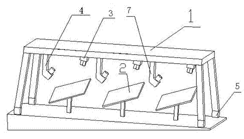
[0076] This embodiment provides a heliostat correction device, which includes a bracket, a laser correction system, and an image processing system,

[0077] The laser correction system is set on the bracket through a positioning device, which includes: at least one laser generator: used to emit laser light to the mirror surface of the heliostat, and the laser beam is reflected by the mirror surface of the heliostat to form a reflection spot on the correction equipment ; At least one image collector: it is set facing the area where the reflected light spot is formed, and is used to collect the image of the reflected light spot; at least one positioning unit: used to determine the spatial position information of the reflected light spot and the laser generator; the image processing system The reflected light spot collected by the image collector is received and the spatial position information of the mirror surface of the heliostat is determined in combination with the spatial po...

Embodiment 2

[0094] In this embodiment, on the basis of Embodiment 1, the positioning device includes a sliding rail arranged on the bracket, and the laser generator and the elbow-shaped support part are provided with a slider.

[0095] After the correction of one heliostat is completed, the positions of the laser generator and the image collector are changed by sliding to realize the correction of other heliostats.

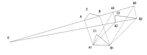
[0096] In this embodiment, each positioning unit includes at least three positioning modules, and the positioning modules are arranged on the support according to the principle that they are not on the same straight line. The at least three positioning modules can determine the positions of at least three points of the support, and the three points can determine a plane, thus further determining the spatial position of the support, and the laser generator and the The relative positional relationship between the image collector and the bracket is known, so that the spatial po...

Embodiment 3

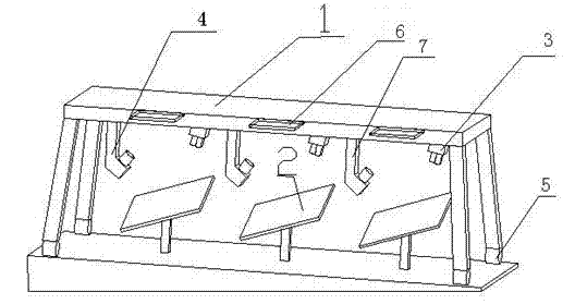
[0101] In this embodiment, on the basis of Embodiment 1, the positioning device includes a 360-degree rotatable rotating mechanism arranged on the bracket, and the laser generator and the elbow support member are arranged on the rotating mechanism .

[0102] After the calibration of one heliostat is completed, the rotation mechanism is used to control the laser generator and the elbow support member to turn to different angles to realize the calibration of other heliostats.

[0103] In this embodiment, each positioning unit includes at least two positioning modules and at least one tilt angle sensing module arranged on the bracket;

[0104] The spatial position of the support can be determined by combining the inclination angle of the support with the positions of two points of the support, and the relative positional relationship between the laser generator and the image collector and the support is known, so as to determine The spatial positions of the laser generator, the ...


PUM


Abstract

A calibrating device for heliostat comprises a support frame (1), a laser calibrating system mounted on the support frame (1), and a movable motion part (5) mounted in the bottom of the support frame (1). When the support frame (1) is set over a heliostat (2) or a group of heliostats, laser beam is emitted to the heliostat surface. The laser beam forms a light spot after being reflected by the heliostat (2). An incidence point of the laser on the heliostat (2) surface can be obtained by processing the image of the light spot. After that an exact spatial location of the heliostat surface is obtained. Then an actual rotation center of the heliostat (2) is also obtained by obtaining several spatial locations of the heliostat surface. The calibrating device can exactly pick up the light spot by using an image acquisition unit (4), and can calibrate a great quantity of heliostats (2) with high efficiency. A method of obtaining the actual rotation center of the heliostat (2) includes using the calibrating device for heliostat.

Description

technical field [0001] The invention relates to a calibration device and method for a solar tracking calibration device, specifically designing a movable heliostat calibration device capable of real-time calibration of the heliostat. Background technique [0002] A heliostat is an optical device used to reflect the light of the sun or other celestial bodies to a fixed direction. It reflects and gathers sunlight to a certain target through a tracking mechanism. The existing heliostats include reflectors, supporting frames, columns , transmission and tracking data processing system and other five major parts. However, during the use of the heliostat, due to the influence of various factors, the accuracy of the tracking mechanism may be reduced, resulting in the reflected light of the sun not being reflected to the target position, which requires the precision of the heliostat to calibrate. [0003] The calibration process of the heliostat is essentially the process of obtain...

Claims


Application Information

Patent Timeline
Patent Type & Authority Applications(China)
IPC IPC(8): G02B7/198G01M11/00F24S50/20
CPCF24J2002/385G01M11/00G02B7/198F24J2/16Y02E10/40F24S2050/25F24S23/77
Inventor 孙海翔朱亮许迪窦新国王威钟强
Owner 深圳市联讯创新工场科技开发有限公司
Why Eureka
Try Eureka