A heliostat calibration device and calibration method

A technology for correcting equipment and heliostats, which is applied to lighting and heating equipment, solar ray concentration, solar collector controllers, etc., can solve the focus position deviation, cumbersome operation process, and the real-time rotation of the heliostat’s rotation axis cannot be realized. Calibration and other problems, to achieve the effect of accurate spatial position and high efficiency

Inactive Publication Date: 2011-12-28
深圳市联讯创新工场科技开发有限公司
View PDF5 Cites 12 Cited by
  • Summary
  • Abstract
  • Description
  • Claims
  • Application Information

AI Technical Summary

Problems solved by technology

[0009] The installation posture measurement device in the above scheme is applied in the process of installing the reflector of the heliostat. After the focus position of the heliostat is determined, the direction of the incident laser light is known, so if the reflected laser light is to be reflected to the focus of the heliostat It must pass through the imaginary point on the laser measuring part. When performing this process, the relative position between the support member and the heliostat must be guaranteed to be a certain value. When the heliostat rotates or due to long-term use When an error occurs during

Method used


Image

  • A heliostat calibration device and calibration method
  • A heliostat calibration device and calibration method
  • A heliostat calibration device and calibration method

Examples


Embodiment 1

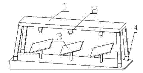
[0055] This embodiment provides a movable heliostat correction device, which includes a bracket, an image acquisition unit and an image processing unit;

[0056] The image acquisition unit is arranged on the support through a positioning device, including:

[0057] At least one camera: used to collect mirror state images of heliostats;

[0058] At least one positioning unit: used to determine the spatial position of the camera;

[0059] The image processing unit is used to receive the image of the state of the mirror surface collected by the camera, and determine the spatial position information of the mirror surface of the heliostat in combination with the spatial position information of the camera.

[0060] In this embodiment, the position detection module includes at least three positioning modules arranged on the support, and the positioning modules are DGPS (Differential Global Positioning System) positioning modules.

[0061] DGPS is the abbreviation of Difference Glob...

Embodiment 2

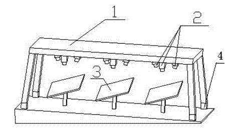
[0090]The difference between this embodiment and Embodiment 1 is that the positioning device includes a 360-degree rotatable rotating mechanism arranged on the bracket, and the image acquisition unit includes a camera, and the camera is arranged on the rotating Institutional.

[0091] In the step a of determining the center of rotation of the heliostat, the rotating mechanism is used to control the camera to take images of the mirror surface of the heliostat under at least two angles to obtain the image of the mirror surface of the heliostat;

[0092] Moreover, after the calibration of one heliostat is completed, the other heliostats can be calibrated by repeating steps b and c by rotating the angle of the camera.

Embodiment 3

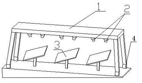
[0094] In this embodiment, the image acquisition unit includes two cameras, and the two cameras are fixed on the bracket through the positioning device.

[0095] In this embodiment, an inclination sensor arranged on the bracket and at least two positioning modules arranged on the camera and the bracket are used instead of the positioning module arranged on the bracket described in the above embodiment. Set at least three positioning modules that are not in the same straight line principle.

[0096] The spatial position of the support and the spatial position of each camera are determined through a combination of an inclination sensor disposed on the support and at least two positioning modules disposed on each camera.

[0097] In the step a of determining the rotation method of the heliostat, the two cameras are used to obtain two images of the mirror state of the heliostat in the current state.


PUM


Abstract

A heliostat calibration device comprises a support frame (1), an image acquisition unit (2) and an image processing unit. The image acquisition unit (2) picks up image information from a heliostat (3) surface directly, and transmits the image information to the image processing unit. The image processing unit obtains the spatial location information of the heliostat (3) surface in accordance with the image information and the spatial location information of the image acquisition unit (2) and of the support frame (1). The image processing unit determines the actual rotation center of the heliostat surface by obtaining several sets of spatial location information of the heliostat surface, and completes calibration of the heliostat (3). The heliostat calibration device acquires image information from the heliostat (3) surface with a high degree of accuracy by means of direct image acquisition by the image acquisition unit. The calibration device is equipped with several movement modes in order to calibrate a great number of heliostats (3) with high efficiency. A method for obtaining the actual rotation center of the heliostat (3) utilizes the heliostat calibration device.

Description

technical field [0001] The invention relates to a calibration device and method for a solar tracking calibration device, and specifically designs a movable heliostat calibration device and a calibration method capable of correcting a heliostat in real time. Background technique [0002] A heliostat is an optical device used to reflect the light of the sun or other celestial bodies to a fixed direction. It reflects and gathers sunlight to a certain target through a tracking mechanism. The existing heliostats include reflectors, supporting frames, columns , transmission and tracking data processing system and other five major parts. However, during the use of the heliostat, due to the influence of various factors, the accuracy of the tracking mechanism may be reduced, resulting in the reflected light of the sun not being reflected to the target position, which requires the precision of the heliostat to calibrate. [0003] The calibration process of the heliostat is essential...

Claims


Application Information

Patent Timeline
IPC IPC(8): G02B7/198G01M11/00F24S50/20
CPCF24J2/38F24J2002/385G01M11/00G02B7/1827G02B7/198F24J2/16Y02E10/40F24S2050/25F24S23/77
Inventor 孙海翔朱亮许迪窦新国王威钟强
Owner 深圳市联讯创新工场科技开发有限公司
Why Eureka
Try Eureka