A cryocooler directly cools a superconducting magnet with a mechanical thermal switch

A technology of superconducting magnets and refrigerators, applied in superconducting magnets/coils, thermal switch components, magnetic objects, etc., can solve the problems of small heat capacity and switch ratio, increased heat leakage, and low heat transfer power , to achieve the effect of ensuring effective utilization, convenient and reliable operation, and strong conduction ability

Active Publication Date: 2011-12-28
NINGBO JANSEN NMR TECH CO LTD
View PDF7 Cites 17 Cited by
  • Summary
  • Abstract
  • Description
  • Claims
  • Application Information

AI Technical Summary

Problems solved by technology

The air-gap thermal switch, such as US Patent 4366680, has a complex system, small heat capacity and switch ratio, resulting in low heat transfer power, and increased heat leakage when the thermal switch is in the off state
The thermal switch disclosed in Chinese patent (publication number 1991287) utilizes vapor-liquid phase transition to realize switch on and off, has strong conduction capability, large switch ratio, and no need for external control. The first and second stages of the refrigerator cause the very limited cooling capacity of the second stage to be transferred to the first stage, reducing the efficiency of the second stage of the refrigerator

Method used


Image

  • A cryocooler directly cools a superconducting magnet with a mechanical thermal switch
  • A cryocooler directly cools a superconducting magnet with a mechanical thermal switch
  • A cryocooler directly cools a superconducting magnet with a mechanical thermal switch

Examples


Embodiment Construction

[0017] The present invention will be further described below in conjunction with accompanying drawing:

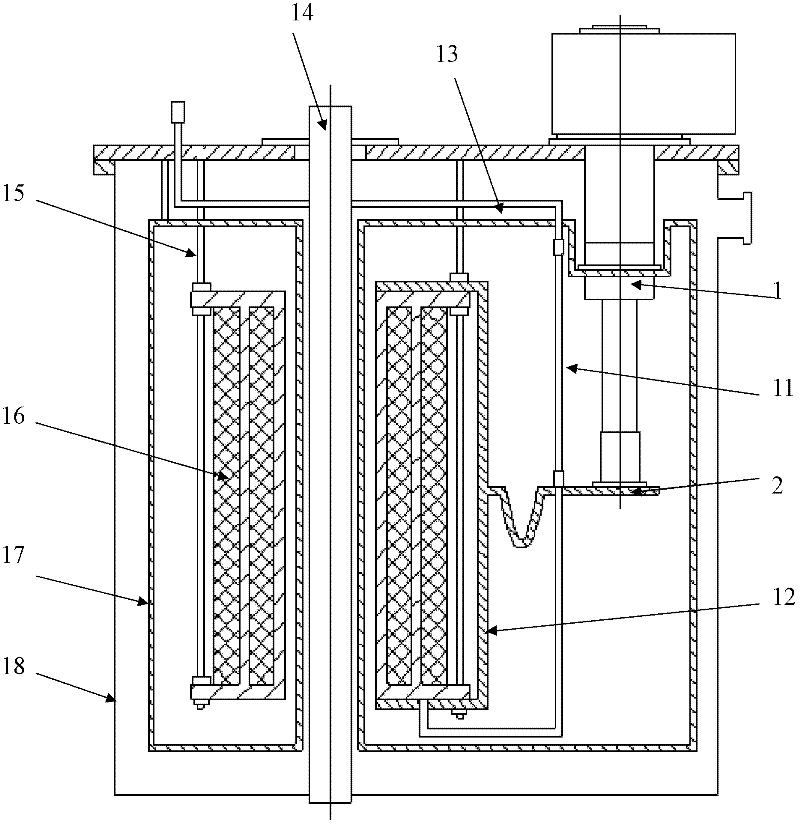
[0018] Such as figure 1 The superconducting magnet system directly cooled by the refrigerator includes the first-stage cold head 1 of the refrigerator, the second-stage cold head 2 of the refrigerator, the high-temperature superconducting current lead 11, the conduction plate 12, the copper wire 13, the room-temperature aperture 14, the support structure 15, and the superconducting magnet. Conductive coil 16, radiation shield 17 and vacuum container 18.

[0019] The mechanical thermal switch for directly cooling the superconducting magnet by the refrigerator of the present invention can be applied to the above-mentioned system for directly cooling the superconducting magnet by the refrigerator.

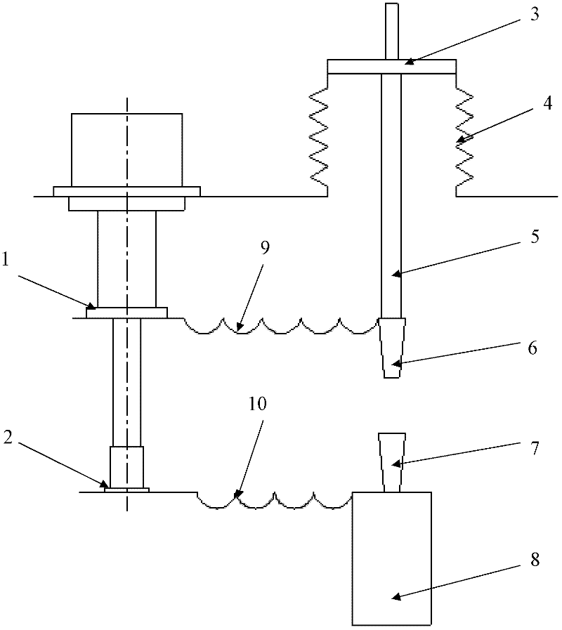
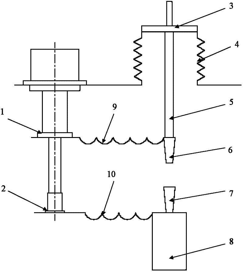
[0020] Such as figure 2 , a mechanical thermal switch for direct cooling of superconducting magnets by a refrigerator, comprising bellows upper flanges 3 bellows 4, glass ...


PUM


Abstract

The invention relates to a mechanical heat switch for a refrigerating machine to directly cool a superconducting magnet, which comprises a corrugated pipe upper flange (3), a corrugated pipe (4), a glass fiber reinforced plastic rod (5), a plug-unplug type electric joint (6), a fixed electric joint (7) and a superconducting magnet (8), wherein the upper end of the glass fiber reinforced plastic rod (5) is connected with the corrugated pipe (4) through the corrugated pipe upper flange (3), the lower end of the glass fiber reinforced plastic rod (5) is provided with the plug-unplug type electric joint (6), the fixed electric joint (7) is arranged under the plug-unplug type electric joint (6) and is arranged on the superconducting magnet (8), the plug-unplug type electric joint (6) is connected with a primary cold head (1) of the refrigerating machine, and a secondary cold head (2) of the refrigerating machine is connected with the fixed electric joint (7). The mechanical heat switch for the refrigerating machine to directly cool the superconducting magnet has the advantages that in the magnet temperature reduction process, the great cold quantity of the primary cold head of the refrigerating machine is utilized, the structure is simple, the operation is convenient and reliable, and the conduction capability is high. When the switch is switched off, no additional heat conduction is caused between the primary cold head and the secondary cold head of the refrigerating machine, and the effective utilization of the secondary cold quantity of the refrigerating machine is ensured.

Description

technical field [0001] The invention provides a mechanical thermal switch for directly cooling a superconducting magnet by a refrigerator, and the thermal switch can be used for fast and effective cooling of a low-temperature superconducting magnet and a high-temperature superconducting magnet. [0002] Background technique [0003] The superconducting magnet directly cooled by the refrigerator adopts the method of cooling the magnet without coolant. Compared with the traditional low-temperature immersion-cooled superconducting magnet, it has the advantages of compact structure, convenient operation and good safety. It has become an important development direction of superconducting magnet technology and opened up a new era for the application of superconducting technology. According to different uses, it is divided into low-temperature superconducting magnets directly cooled by refrigerators and high-temperature superconducting magnets. Figure 1 Direct cooling of superco...

Claims


Application Information

Patent Timeline
Patent Type & Authority Applications(China)
IPC IPC(8): H01H37/38H01H37/02H01F6/04
Inventor 汤洪明
Owner NINGBO JANSEN NMR TECH CO LTD
Why Eureka
Try Eureka