A kind of plastic encapsulation mold and upper lead wire and lower lead wire therein

A plastic sealing mold and lead bar technology, which is applied in the direction of electrical components, semiconductor/solid-state device manufacturing, circuits, etc., can solve the problems of high matching requirements, pin beading or plastic sealing compound residue, high matching requirements of plastic sealing molds and lead frames, etc. , to achieve the effect of reducing manufacturing cost

Active Publication Date: 2011-12-28
深圳市华龙精密模具有限公司 +3
View PDF2 Cites 3 Cited by
  • Summary
  • Abstract
  • Description
  • Claims
  • Application Information

AI Technical Summary

Problems solved by technology

[0005] The technical problem to be solved by the present invention is to provide a method that can seal the device pins during the plastic sealing process in view of the high requirements for the cooperation between the plastic sealing mold and the lead frame in the prior art, and the defects that the pin beading or the plastic sealing compound residues are prone to occur. plastic mold
[0006] Another technical problem to be solved by the present invention is to provide a device that can seal the device during the plastic sealing process in view of the high requirements for the cooperation between the plastic sealing mold and the lead frame in the prior art, and the defects that the pin beading or the residual plastic sealing compound are prone to occur. Top and bottom leads in plastic mold for pins

Method used


Image

  • A kind of plastic encapsulation mold and upper lead wire and lower lead wire therein
  • A kind of plastic encapsulation mold and upper lead wire and lower lead wire therein
  • A kind of plastic encapsulation mold and upper lead wire and lower lead wire therein

Examples


Embodiment Construction

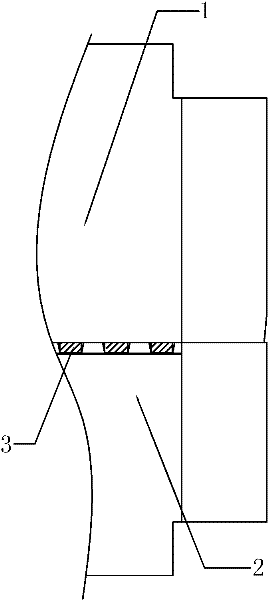
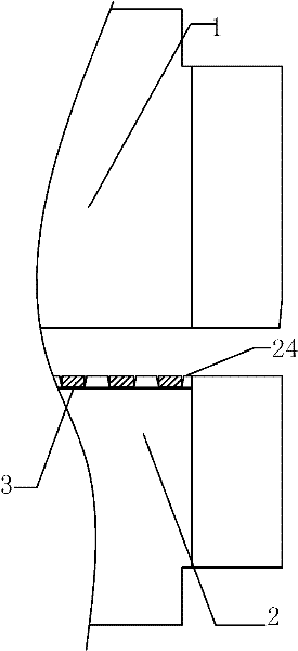
[0030] Figure 2A It is a structural schematic diagram of the closed state of the upper lead wire and the lower lead wire in the plastic sealing mold according to the present invention; Figure 2B It is a structural schematic diagram of the separation state of the upper lead bar and the lower lead bar in the plastic packaging mold according to the present invention. Such as Figure 2A and Figure 2B As shown, the upper lead bar 1 and the lower lead bar 2 include 16 packaging positions, each of which can package a device. The upper and lower lead bars have a structure of insertion, that is to say, relative to the position of the lead groove of the lower lead bar, the upper lead bar is provided with a raised part, and the raised part just blocks the notch part of the lead groove when it is closed. , Seal the lead groove from the top and upper side. Although in Figure 2A and 2B In the illustrated embodiment, each package has three lead slots, correspondingly each device ha...


PUM


Abstract

The invention relates to a plastic packaging die and an upper lead strip and a lower lead strip therein. The plastic packaging die comprises the upper lead strip (1) and the lower lead strip (2) for sealing a tube pin (3) of a device in the plastic packaging process of the device; the upper surface of the lower lead strip is provided with a lead slot (20) for accommodating the tube pin; and the upper lead strip is provided with a strip protrusion (10) at the position relative to the lead slot in the lower lead strip, so that the protrusion seals the lead slot from the top and the upper lateral surface of the lead slot when the upper lead strip is pressed on the lower lead strip. The plastic packaging die has the advantages that: the upper and lower lead strips in the plastic packaging diehave opposite inserted structures, and the upper lead strip is provided with the protrusion part at the corresponding position of the tube pin and just pressed on the front side of the tube pin of the device during closing, so that a material is not leaked at the front side and the reverse side, and no residual plastic packaging material is left on the tube pin of the device. In addition, the precision requirement for the tube pin is low on selection of the lead frame, so that the manufacturing cost of the lead frame can be reduced.

Description

technical field [0001] The invention relates to integrated circuit packaging, more specifically, to a plastic sealing mold for packaging semiconductor or integrated circuit components. Background technique [0002] In the use of semiconductor and integrated circuit components, it is generally required that the residual amount of plastic encapsulant on the pins be as small as possible. If there is a lot of plastic sealant remaining on the pins and sides of the device, it will cause false soldering and poor contact. If there are severe plastic seal residues on the pins of the device, it needs to be removed by high-pressure water spraying and flushing, which will increase the manufacturing cost virtually, and the processing result is not ideal. [0003] Figure 1A and Figure 1B Shown is a structural schematic diagram of the upper lead bar 1 and the lower lead bar 2 in the prior art plastic packaging mold. in, Figure 1A is a schematic diagram of the closed state; Figure 1...

Claims


Application Information

Patent Timeline
IPC IPC(8): H01L21/56
Inventor 羊勇何勇徐勇
Owner 深圳市华龙精密模具有限公司
Why Eureka
Try Eureka