cutting tool

A cutting tool and cutting head technology, which is applied in thread cutting tools, manufacturing tools, drilling accessories, etc., can solve the problems of cutting tool rigidity reduction, cutting head vibration, thread tooth defect, etc., to reduce vibration and reduce replacement frequency , Reduce the effect of thread tooth defect

Inactive Publication Date: 2011-12-28
OSG
View PDF6 Cites 6 Cited by
  • Summary
  • Abstract
  • Description
  • Claims
  • Application Information

AI Technical Summary

Problems solved by technology

[0007] However, both the main body and the cutting head of the above-mentioned conventional connected cutting tool are made of cemented carbide, so the threads of the male or female thread connecting the main body and the cutting head are likely to be damaged by shock caused by vibration. defect
On the other hand, when the threads of the male or female threads are damaged, the main body or the cutting head with the defective threads must be replaced, so the effect of reducing the amount of scrap is not good.
In addition, the rigidity of the overall cutting tool is lower than that of the integral cutting tool, so the vibration of the cutting head is easy to occur during cutting.

Method used


Image

  • cutting tool
  • cutting tool
  • cutting tool

Examples


Embodiment Construction

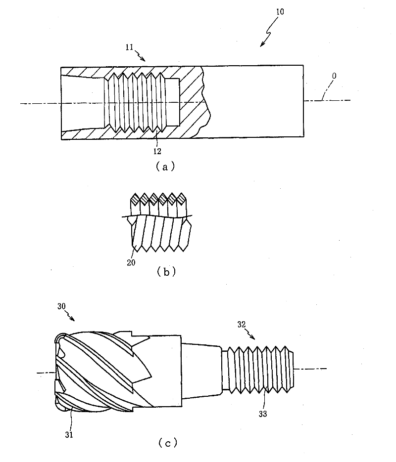
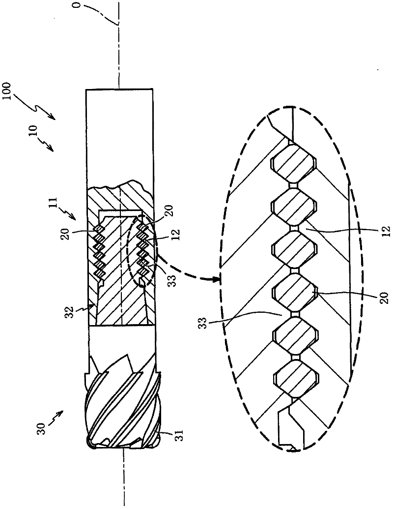
[0024] The preferred embodiments of the present invention are described below in conjunction with the accompanying drawings. combine first figure 1 The structure of each part of the cutting tool 100 in one embodiment of the present invention will be described. figure 1 (a) is a side view of the main body 10 constituting the cutting tool 100 according to an embodiment of the present invention, figure 1 (b) is a side view of the high-precision screw lining 20, figure 1 (c) is a side view of the cutting head 30 . in, figure 1 (a) shows the female thread part 11 of the main body part 10 in a cross-sectional manner, figure 1 (b) schematically shows the high-precision threaded bushing for simplicity, and at the same time shows a part of the high-precision threaded bushing 20 in a cross-sectional manner ( figure 1 (b) upper side).

[0025] Such as figure 1 As shown in (a), the main body portion 10 is made of a cemented carbide formed by press-sintering tungsten carbide...


PUM


Abstract

The present invention provides a cutting tool capable of reducing the amount of scrapped body parts and cutting heads and reducing vibration during cutting. A cutting tool (100) has a high-precision screw bushing (20) made of steel lower in rigidity than cemented carbide between a male thread portion (32) and a female thread portion (11). Thus, the external thread portion (32) and the internal thread portion (11) can be prevented from contacting each other, thereby reducing the loss of the thread teeth (33) of the external thread portion (32) and the thread threads (12) of the internal thread portion (11). In addition, since the rigidity of steel is lower than that of cemented carbide, it is possible to buffer the cutting head (30) against the main body by inserting a high-precision screw bushing (20) between the male thread portion (32) and the female thread portion (11). (10) Vibration.

Description

technical field [0001] The present invention relates to a cutting tool that can be attached and detached between a main body and a cutting head, and more particularly, to a cutting tool that can reduce scrapping of the main body and the cutting head and reduce vibration during cutting. Background technique [0002] Conventionally, a cutting tool made of cemented carbide is known as a cutting tool that is driven to rotate by a machining center and cuts a workpiece. A cutting tool made of cemented carbide has higher rigidity and less deflection than a cutting tool made of high-speed tool steel, and thus is more advantageous in terms of machining accuracy of cutting. [0003] However, compared with high-speed tool steel, cemented carbide has low toughness and is prone to chipping. Therefore, in the case of a monolithic (knife handle integrated) cutting tool made of cemented carbide, the entire cutting tool must be replaced every time the cutting edge is damaged, resulting in a...

Claims


Application Information

Patent Timeline
Patent Type & Authority Applications(China)
IPC IPC(8): B23C5/10B23B51/00B23G5/06B23Q11/00
CPCB23C5/10B23B31/1107B23C2210/03B23C2210/02B23B31/1122Y10T407/1932
Inventor 大泽二朗远藤康幸永井保
Owner OSG
Why Eureka
Try Eureka