
Novel compensating device for boring cutter

A tool compensation and boring technology, which is applied in the direction of manufacturing tools, boring/drilling, boring machine/drilling machine parts, etc., can solve the problems of complexity and low cutting force, simplify the structure of the machine tool, and increase the moving inertia of the tool Effect

Active Publication Date: 2012-01-04
山东普惠动力科技有限公司
View PDF9 Cites 16 Cited by
  • Summary
  • Abstract
  • Description
  • Claims
  • Application Information

AI Technical Summary

Problems solved by technology

This mechanism is more complicated, and the cutting force is not large (<400N)

Method used


Image

  • Novel compensating device for boring cutter
  • Novel compensating device for boring cutter
  • Novel compensating device for boring cutter

Examples


Embodiment Construction

[0026] The present invention will be further described below in conjunction with the accompanying drawings.

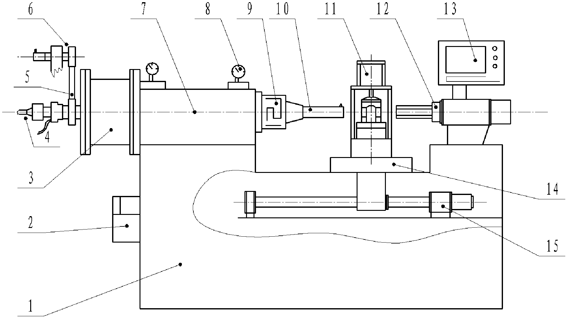
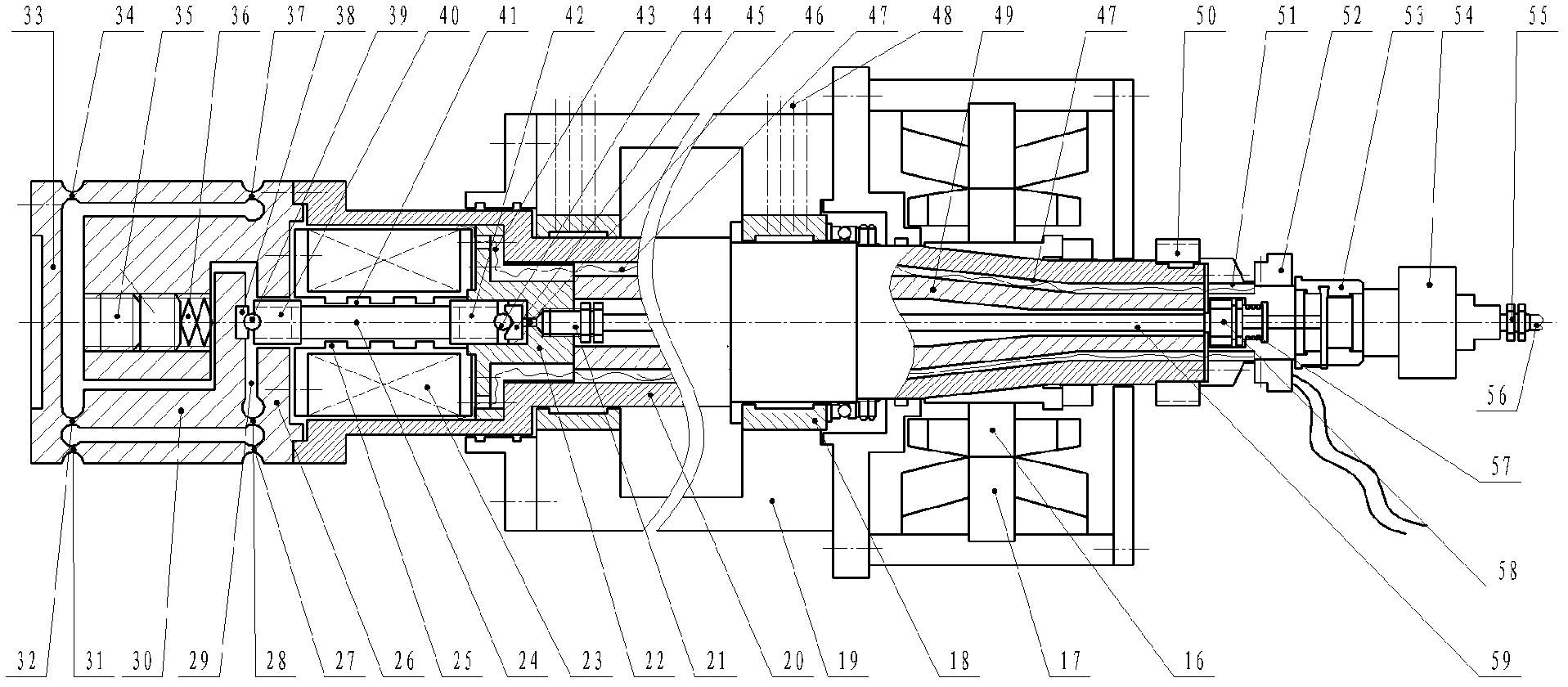
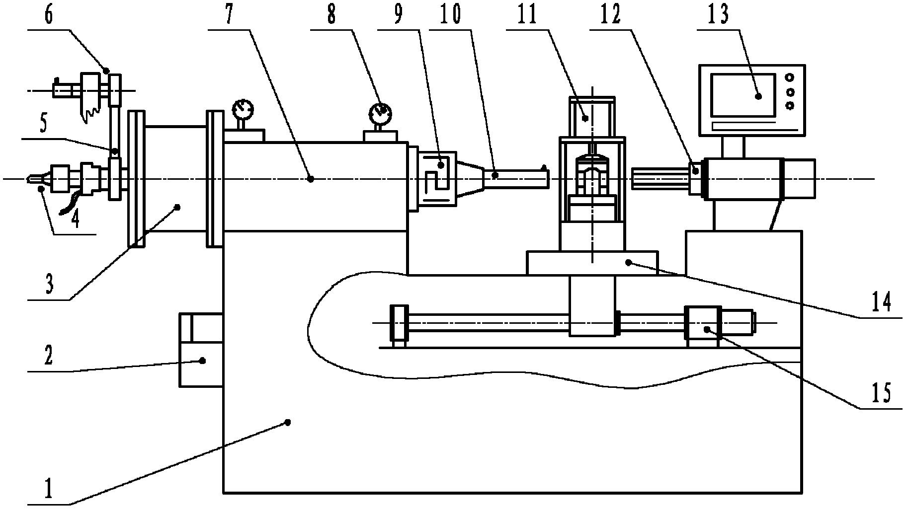
[0027] A new type of compensation device for boring tools, which includes a machine bed 1 and a small hole throttling high-speed precision hydrostatic boring head 7, wherein the bed 1 is equipped with a spindle drive motor 3, a spindle pulse encoder 6, and a workpiece Clamping mechanism 11, workpiece positioning mechanism 12, numerical control device 13, longitudinal servo motor drive system 15, automatic lubricating device 2, spindle drive motor 3 is connected with small hole throttling high-speed precision hydrostatic boring head 7, such as figure 1 shown. Such as figure 1 , figure 2 As shown, in the main shaft 20 of lathe, be provided with giant magnetostrictive actuator GMA, giant magnetostrictive actuator GMA cooling device 4 and distribution by installing giant magnetostrictive bar stock 24 and solenoid 23 etc. Electrical device; the front end of the small-ho...


PUM


Abstract

The invention discloses a novel compensating device for a boring cutter, which comprises a machine tool bed (1) and an orifice restriction type high-speed precision liquid static pressure boring head (7), wherein a main shaft drive motor (3), a main shaft pulse coder (6), a workpiece clamping mechanism (11), a workpiece positioning mechanism (12), a numerical control device (13), a longitudinal servo motor drive system (15) and an automatic lubricating device (2) are arranged on the arranged on the machine tool bed (1); the main shaft drive motor (3) is connected with the orifice restriction type high-speed precision liquid static pressure boring head (7); and a super magnetostriction actuator, a super magnetostriction actuator cooling device (4) and a power distribution device of the supper magnetostriction actuator are arranged in a main shaft (20) of a machine tool. The novel compensating device for the boring cutter has the characteristic that the axial displacement generated by the super magnetostriction actuator is transformed into the radial translation displacement of the boring cutter through an L-shaped right angle lever and a four-link combined flexible hinge mechanism,thus the radial translation feeding of the boring cutter is realized.

Description

technical field [0001] The invention relates to a novel boring tool compensation device, which can be used for tool wear compensation and boring diameter adjustment in the boring process, and can also be used for precision boring of special-shaped pin holes of pistons. Background technique [0002] At present, domestically and internationally, there are five representative methods for realizing boring tool compensation, and these methods all have some shortcomings: [0003] Patent No.: 98112446, Publication No.: 1232732A Chinese patent discloses a "special-shaped pin-hole boring device", which adopts the mechanical mechanism of "longitudinal stepping motor + driving rod + push rod", the machine tool structure is relatively complicated, and It is not suitable for the application of high-response tool compensation. [0004] Patent No.: 200510044793, Publication No.: 1743111A Chinese patent discloses "a boring machine for machining special-shaped curved surface holes", which h...

Claims


Application Information

Patent Timeline
IPC IPC(8): B23B41/04B23B47/00B23B47/18
Inventor 翟鹏秦磊王朋李瑞珍王萌曲孟孟
Owner 山东普惠动力科技有限公司
Learn More