

Dyeing cylinder structure for beam dyeing machine
A warp beam dyeing and cylinder technology, which is applied to the processing of textile material carriers, liquid/gas/steam yarn/filament processing, etc., can solve the problems of large energy consumption, high energy consumption, and large dyeing liquid capacity, and achieve effective Effects of space reduction, energy saving, and usage reduction
- Summary
- Abstract
- Description
- Claims
- Application Information
AI Technical Summary
Problems solved by technology
Method used
Image

Examples
Embodiment Construction
[0015] In order to enable the examiners of the patent office, especially the public, to understand the technical essence and beneficial effects of the present invention more clearly, the applicant will describe in detail the following in the form of examples, but none of the descriptions to the examples is an explanation of the solutions of the present invention. Any equivalent transformation made according to the concept of the present invention which is merely formal but not substantive shall be regarded as the scope of the technical solution of the present invention.
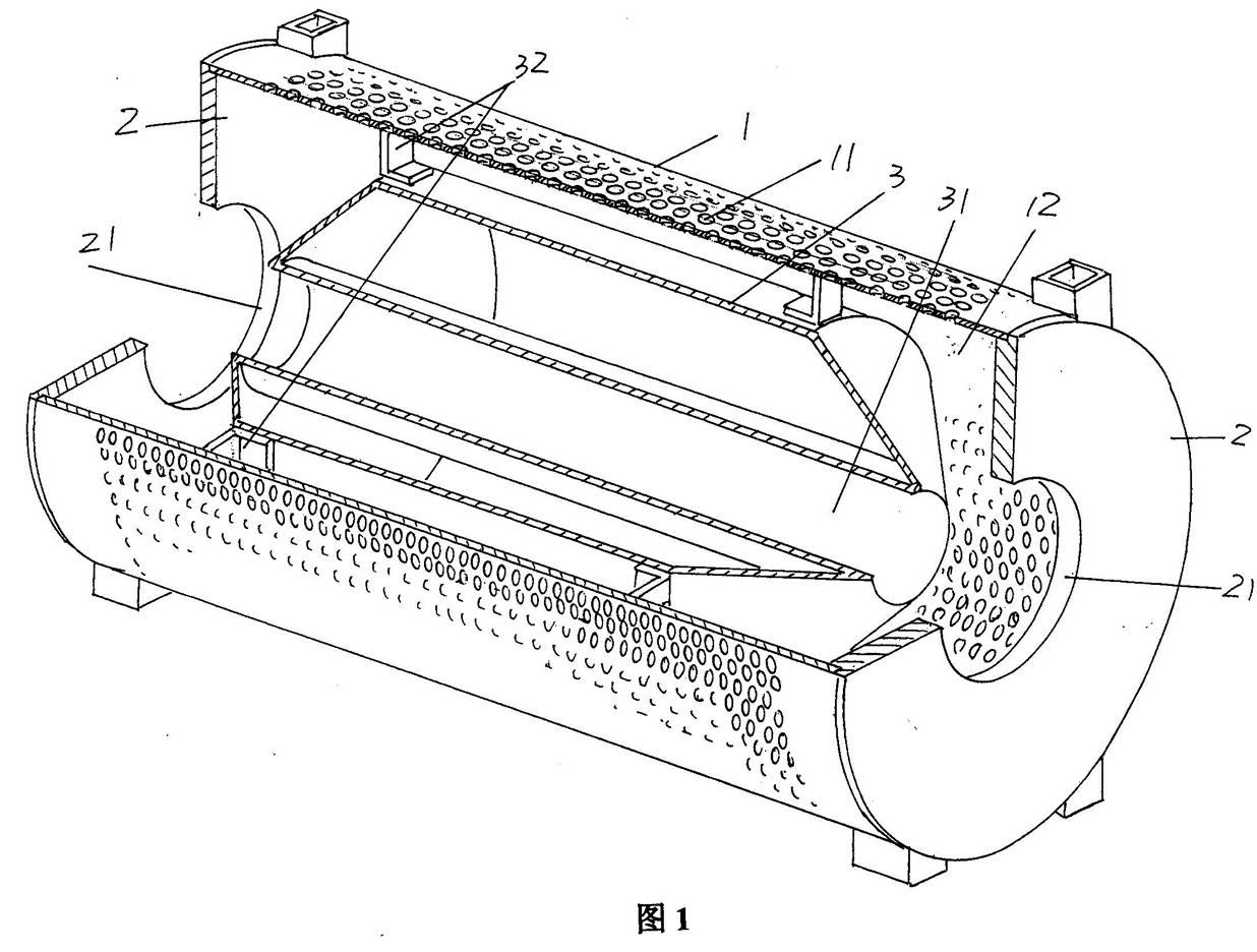
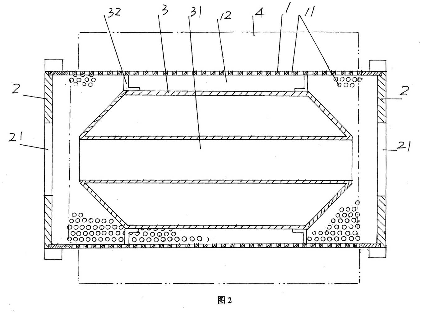
[0016] Please see figure 1 with figure 2 , a drum or a cylinder body 1 with a cylindrical structure is given, and a liquid hole communicating with the cavity 12 (the cavity 12 of the cylinder body 1) is opened on the cylinder body 1 in a dense state. 11. Both ends of the cylinder body 1 are respectively fixed with a sealing plate 2, the end of the aforementioned cavity 12 is closed by the sealing pla...
PUM
 Abstract
Description
Claims
Application Information