Eureka AIR delivers breakthrough ideas for toughest innovation challenges, trusted by R&D personnel around the world.

Distributed Server Liquid Cooling System

A distributed server and liquid cooling technology, applied in the field of server heat exchange, can solve problems such as limited space, large occupied space, and huge system

Active Publication Date: 2018-12-18
深圳市至佳生活网络科技有限公司 +2
View PDF6 Cites 5 Cited by
  • Summary
  • Abstract
  • Description
  • Claims
  • Application Information

AI Technical Summary

Problems solved by technology

[0003] The Chinese patent literature publication number is CN103052304A, which discloses a modularized cooling system for server cabinets. This solution integrates the liquid cooling box inside the server cabinet, the water cooling radiator, the air radiator in the cabinet, and the first liquid storage tank. In the server cooling cabinet, the liquid cooling box includes a finned heat exchanger, a plate heat exchanger and the first water pump integrated in a box. The whole system is very large and takes up a lot of space. The server cooling cabinet is reserved for erection Very limited space to install servers and other network equipment

Method used


Image

  • Distributed Server Liquid Cooling System
  • Distributed Server Liquid Cooling System
  • Distributed Server Liquid Cooling System

Examples


Embodiment 1

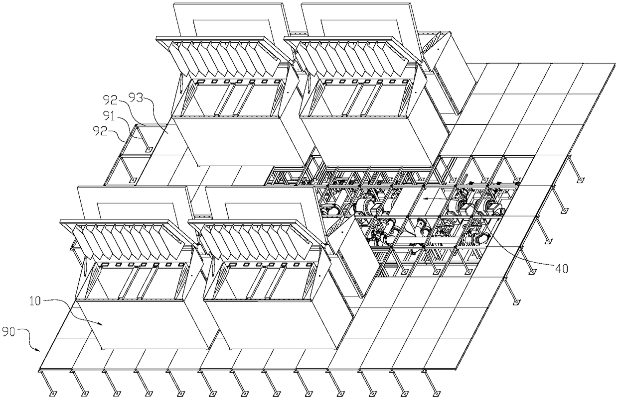
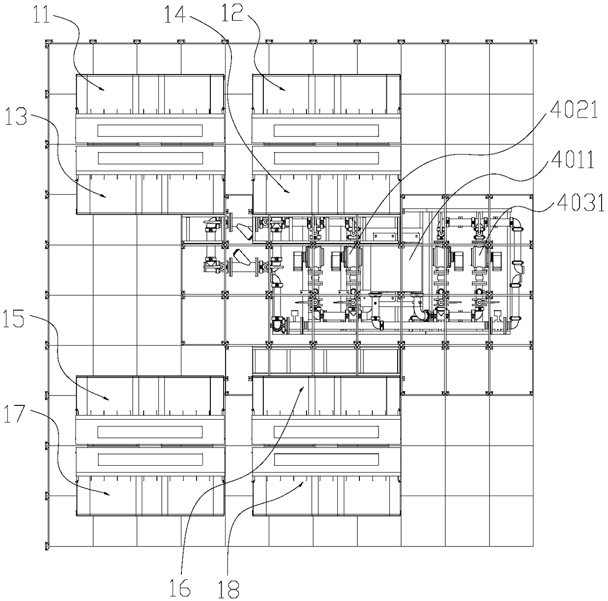
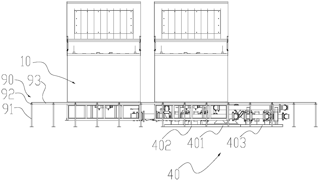
[0088] Example 1, such as figure 1 , figure 2 , image 3 As shown in the standard 8-cabinet distributed server liquid cooling system, the distributed server liquid cooling system hosts are arranged horizontally along the passage side of the aisle in the middle aisle area of ​​the two sets of distributed server liquid cooling system cabinets. This layout can be reserved Increase the installation area of ​​the cabinets of the distributed server liquid cooling system. At the same time, core components such as filters, pumps, and heat exchangers that may need to be maintained or replaced frequently are placed under the static floor of the aisle for easy maintenance.

Embodiment 2

[0089] Example 2, such as Figure 8 , Figure 9 , Figure 10 As shown, in the standard 4-cabinet distributed server liquid cooling system, the distributed server liquid cooling system mainframe is longitudinally arranged in the middle aisle area of ​​the two sets of distributed server liquid cooling system cabinets along the vertical direction of the passing side of the aisle. This layout method Wider aisles can be reserved. The installation area available for liquid-cooled server cabinets will be slightly reduced. At the same time, core components such as filters, pumps, and heat exchangers that may require frequent maintenance or replacement are placed under the static floor of the aisle for easy maintenance. The first refrigerant liquid outlet and liquid return port are arranged directly under the electrostatic floor in the area closest to the cabinet liquid inlet and cabinet liquid outlet of the distributed server liquid cooling system, which can reduce the difficulty of...


PUM


Abstract

A liquid cool system of distributed server is disclosed and includes at least one cabinet and a heat exchanger core, a first refrigerant driving pump and a first refrigerant filter are arranged between the first refrigerant outlet of the heat exchange machine core and the liquid inlet of the cabinet, the liquid inlet and the liquid outlet of each of the first refrigerant driving pumps are respectively provided with a first refrigerant butterfly valve, and the liquid inlet and the liquid outlet of each of the first refrigerant filters are respectively provided with a first refrigerant butterflyvalve; The cabinet is provided with a baffle plate and a return mechanism which divide the first refrigerant liquid level into at least two independent regions, each independent region is communicated with a return liquid inlet on the return mechanism, and the return liquid outlet of the return mechanism is communicated with the liquid outlet of the cabinet. As that heat exchange movement is horizontally arranged along the minimum height thereof, the pipeline is smoothly arrange and the pipeline resistance is reduced; At that same time, the liquid level is divide into at least two independentareas to avoid liquid level channeling, and the heat-absorbing first refrigerant can be quickly return to the heat exchange core through the reflux mechanism, and the heat dissipation efficiency is high.

Description

technical field [0001] The invention relates to the technical field of server heat exchange, in particular to a distributed server liquid cooling system. Background technique [0002] With the rapid development of cloud computing, the data density is getting higher and higher, and its requirements for heat dissipation and energy saving of servers for data operation management are also getting higher and higher. Liquid cooling technology is the comprehensive energy efficiency ratio of PUE-powerusage efficiency among many new server cooling technologies. It is a relatively low-level technology. A lower PUE value means the technology is more energy efficient. [0003] The Chinese patent literature publication number is CN103052304A, which discloses a modular server cabinet cooling system. This solution integrates the liquid cooling box inside the server cabinet, the water cooling radiator, the air radiator in the cabinet, and the first liquid storage tank. In the server cooli...

Claims


Application Information

Patent Timeline
IPC IPC(8): H05K7/20
CPCH05K7/20272H05K7/2079
Inventor 李锋
Owner 深圳市至佳生活网络科技有限公司
Why Eureka
Eureka Blog
Learn More