Linear motor-driven plunger pump

A linear motor and drive column technology, applied in the direction of machines/engines, pumps, mechanical equipment, etc., can solve the problems of large inertial force and large rated thrust of the linear motor, and achieve the effect of reducing the number and enhancing the pollution resistance.

Inactive Publication Date: 2012-01-04
BEIJING UNIV OF TECH
View PDF6 Cites 22 Cited by
  • Summary
  • Abstract
  • Description
  • Claims
  • Application Information

AI Technical Summary

Problems solved by technology

The inertial force consumed by the coil mover and slider is relatively la

Method used


Image

  • Linear motor-driven plunger pump
  • Linear motor-driven plunger pump
  • Linear motor-driven plunger pump

Examples


Embodiment 1

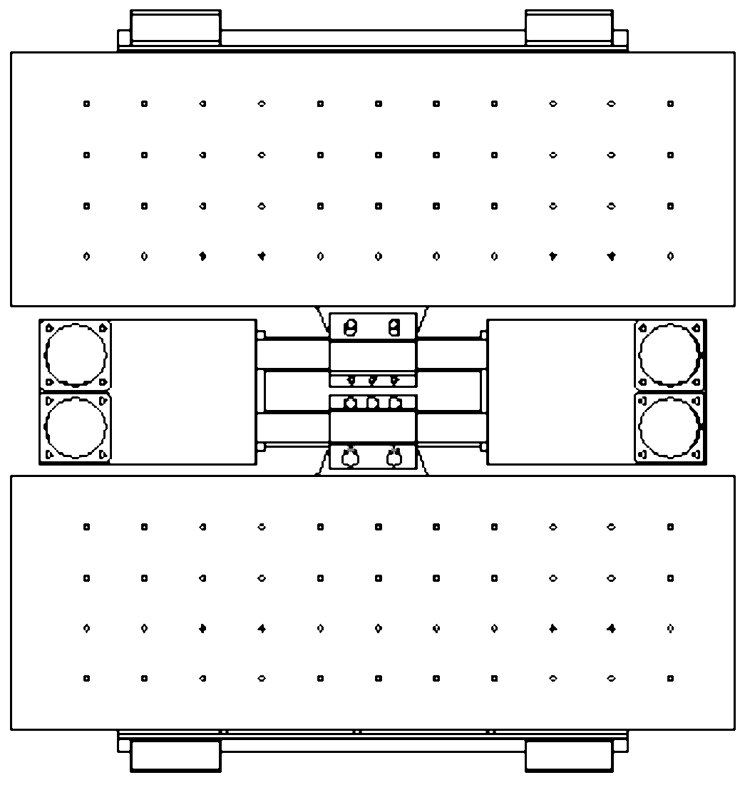
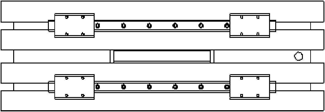
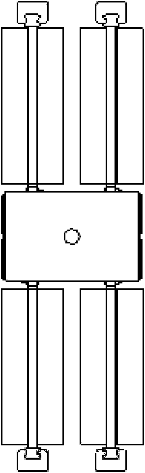
[0047] The linear motor driven plunger pump includes a mechanical part and an electrical part, and the mechanical part and the electrical part are connected by a linear motor mover. Taking a plunger pump with four linear motors as an example, each linear motor of the linear motor driven plunger pump is driven by a corresponding driver, and the controller outputs control signals with a certain phase difference to the four drivers. After the control signal is amplified, it is output to the corresponding linear motor stator 11 respectively, thereby driving the corresponding linear motor mover 9, and the mover 9 drives the plunger rod 6 to reciprocate and linearly move in a certain motion plan through the compression flange 13 .

[0048] A group of coil-type stators 11 drives the permanent magnet mover 9 to reciprocate on the fixed slider 8, the permanent magnet mover 9 drives the double-acting plunger rod 6 to reciprocate through the compression flange 13, and the double-acting p...

Embodiment 2

[0053] The two cylinders of the plunger pump are symmetrical, and both adopt the structure of cylinder I. The inner sides of the two suction through holes of the two cylinders are connected through the suction connecting pipe, and the outer ends of the two suction through holes are connected with the suction main pipe. The inner side of the hole is connected by the extruding connecting pipe, and the outer end of the extruding through hole is connected with the extruding main pipe, so as to realize the communication between the suction circuit and the extruding circuit of the two cylinders. The beneficial effect of the cylinder structure is that it can adapt to the field application environment of the plunger pump, and can suck liquid from one end of the plunger pump and press liquid from the other end or suck liquid and press liquid from the same end of the plunger pump.

[0054] Through material reselection and structural fine-tuning, the plunger pump can be used as the workin...


PUM


Abstract

The invention relates to a linear motor-driven plunger pump. The mechanical part of the plunger pump comprises a cylinder body I, a cylinder body II, flow distribution valves, an in-sucking communication pipe, out-pressing communication pipes, compacting flanges, plunger rods, linear motor stators, linear motor rotors and guide rails; and the electric part mainly consists of linear motors, a controller, drivers and a position feedback device. The linear motor-driven plunger pump is characterized in that a group of coil-type stators drive a permanent magnet rotor in a combinational way, thus realizing high thrust output of the linear motors. Each flat-type linear motor drives two plungers at the two ends of one plunger rod, and while the double-action plunger rod reciprocates, one end of the double-action plunger rod sucks water and at the same time the other end of the double-action plunger rod presses water. The two cylinders realizes the effective communication between the water sucking loop and water pressing loop of the plunger pump by means of the in-sucking communication pipe and the two out-pressing communication pipes. Each plunger hole is communicated with a flow distribution valve consisting of an in-sucking valve and an out-pressing valve. The electric part controls the out-of-phase movement of the linear motors, thus ensuring the stable combinational flow output of the pump. The linear motor-driven plunger pump disclosed by the invention has the advantages of less mechanical transmission links and high system efficiency and reliability.

Description

technical field [0001] The invention relates to a plunger pump driven by a linear motor, which belongs to the pump category and is suitable for hydraulic systems in which seawater, mineral oil, etc. are used as working media, and is widely used in industries such as deep sea exploration, oil exploitation, food processing, and ships. prospect. technical background [0002] Traditional hydraulic transmission uses mineral oil as the working medium, but mineral oil is flammable, leaks and discharges pollute the environment, is easy to oxidize and deteriorate after long-term use, has poor shear resistance, viscosity is greatly affected by oil temperature, low reuse rate, waste Disadvantages such as difficult to deal with, especially with the gradual depletion of oil resources in the future, mineral oil will become a rare resource, the cost will increase sharply, and the development of hydraulic transmission technology will face severe challenges. [0003] Water-hydraulic transmi...

Claims


Application Information

Patent Timeline
IPC IPC(8): F04B17/03
Inventor 聂松林董武涛李志海尹方龙喻国哲
Owner BEIJING UNIV OF TECH
Why Eureka
Try Eureka