On-load detection method and device for intelligent optical fiber electric energy meter in substation

A technology of smart substation and smart energy meter, which is applied in the direction of measuring devices, measuring electrical variables, instruments, etc., can solve problems such as troublesome installation and maintenance, cumbersome, non-chargeable, real-time detection and calibration with load, etc., and achieve simplified detection work, The effect of improving economy

Active Publication Date: 2012-01-04
STATE GRID HUNAN ELECTRIC POWER CO LTD ELECTRIC POWER SCI RES INST +1
View PDF8 Cites 18 Cited by
  • Summary
  • Abstract
  • Description
  • Claims
  • Application Information

AI Technical Summary

Problems solved by technology

Correspondingly, a calibration device for smart fiber-optic energy meters has also been developed, but at present almost all calibration devices are indoor detection devices, and it is necessary to remove the smart fiber-optic energy meters in smart substations from the site and bring them back to the laboratory Verification, instead of real-time detection and verification of live and loaded loads at the substation site like traditional electric energy meters
This method is more complicated, cumbersome, and costly. In addition, most of the methods for indoor calibration of smart energy meters are to send voltage and current signals to the detected smart energy meters by the energy meter calibrator, and then compare the calculated electricity with the measured ene...

Method used


Image

  • On-load detection method and device for intelligent optical fiber electric energy meter in substation
  • On-load detection method and device for intelligent optical fiber electric energy meter in substation
  • On-load detection method and device for intelligent optical fiber electric energy meter in substation

Examples


Embodiment Construction

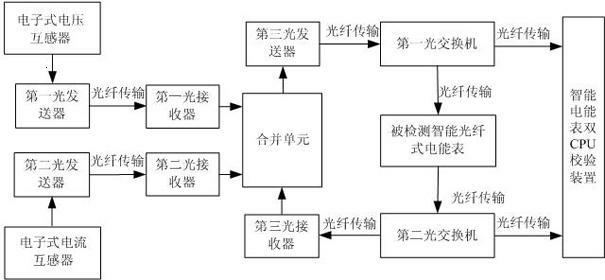
[0021] Such as figure 1 As shown, the electronic voltage transformer and electronic current transformer measure the actual operating voltage and current on site, and the voltage digital signal output by the electronic voltage transformer is transmitted to the first optical receiver through the first optical transmitter through the optical fiber, The current digital signal output by the electronic current transformer is sent to the second optical receiver through the second optical transmitter through the optical fiber. The digital voltage and current signals are converted into IEC61850-9-2LE message format in the merging unit, and packed into a group of data frames, and transmitted to the first optical switch through the third optical transmitter through an optical fiber, and are It is divided into two optical signals with the same transmission content. One optical signal from the first optical switch is transmitted to the detected smart fiber optic energy meter, and the actu...


PUM


Abstract

The invention relates to an on-load detection method and an on-load detection device for an intelligent optical fiber electric energy meter in a substation. The method comprises the following steps of: measuring actual field running voltage and actual field running current by using an electronic voltage transformer and an electronic current transformer; outputting a digital signal, and transmitting to a combination unit; processing and allocating the digital signal by using the combination unit, and transmitting to a first optical switch; dividing the output of the first optical switch into two paths, and respectively transmitting to a detected intelligent optical fiber electric energy meter and an intelligent electric energy meter dual-central-processing-unit (CPU) calibration device; dividing the output of the detected intelligent optical fiber electric energy meter in operation into two paths, and respectively connecting to the combination unit and the intelligent electric energy meter dual-CPU calibration device by using a second optical switch; comparing standard electric energy with detected electric energy; and calculating a metering error of the detected intelligent optical fiber electric energy meter to complete the detection of the detected intelligent optical fiber electric energy meter in operation. The invention has the advantages that: the method and the device are convenient, simple, high-efficient, safe and the like.

Description

technical field [0001] The invention belongs to the field of electric energy metering, and in particular relates to a method and device for detecting a load of an optical fiber electric energy meter, which is used for on-load detection of an intelligent optical fiber electric energy meter operating in an intelligent substation. Background technique [0002] In recent years, with the maturity of technologies such as substation intelligent switches, photoelectric transformers, online status detection of primary operating equipment, substation operation training simulation technology, and the development and application of computer high-speed networks in real-time systems, information collection for substations has become more and more mature. , transmission and measurement, metering, protection and other aspects to achieve digital processing provides a theoretical and material basis. With the development of optoelectronics, microelectronics, computer and communication technol...

Claims


Application Information

Patent Timeline
IPC IPC(8): G01R35/04
Inventor 徐先勇罗志坤欧朝龙万全向华李恺
Owner STATE GRID HUNAN ELECTRIC POWER CO LTD ELECTRIC POWER SCI RES INST
Why Eureka
Try Eureka