Front steel turning device of cogging mill

A billet cutting machine and steel turning technology, which is applied in the direction of workpiece manipulation, etc., can solve the problems of high technical level requirements for workers, difficulty in aligning the position of turning steel, and potential safety hazards, etc., to achieve accurate and reliable translation and turning actions, and stable and accurate lifting , the effect of simple structure

Active Publication Date: 2012-01-11
HUATIAN ENG & TECH CORP MCC
View PDF8 Cites 6 Cited by
  • Summary
  • Abstract
  • Description
  • Claims
  • Application Information

AI Technical Summary

Problems solved by technology

[0003] The billet opening machine needs to roll the billet, oval billet or special-shaped billet in both horizontal and vertical directions, and the billet must be turned 90 degrees. At present, the most widely used turning device in China is the hook-type turning device, which is hooked by a manual driving hook. On the bottom side of the billet, the billet is turned over after being lifted. This turning method has the following problems: 1. It is difficult to align the position of the turning steel, and the position after turning the steel is uncertain
Generally speaking, the driver must cooperate with the workers below to put the hook in place, which requires a higher technical level of the workers; 2. There are potential safety hazards
The site environment is harsh, especially the high temperature of more than 1,000 degrees for the billet is a test for the worker's operation. Because of the high ambient temperature, it is more difficult for the worker to choose the exact flipping position when flipping; 3. For elliptical billets, the degree of deformation Larger blanks cannot be applied; 4. Long turning time and low efficiency

Method used


Image

  • Front steel turning device of cogging mill
  • Front steel turning device of cogging mill
  • Front steel turning device of cogging mill

Examples


Embodiment Construction

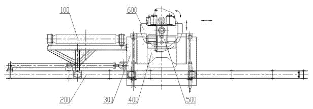
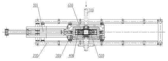
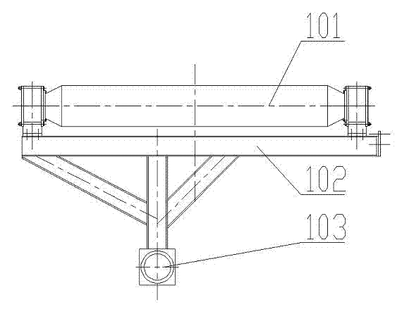
[0035] (refer to figure 1 with figure 2 ) A steel turning device before a blanking machine, including a replacement roller table 100, a base 200, a translation frame 300, a lifting mechanism 400, a turning mechanism 500, and a clamping roller mechanism 600, wherein the replacement roller table 100 is fixedly connected to the translation frame 300, And can move linearly along the base 200, the lifting mechanism 400 is located in the translation frame 300, and the overturning mechanism 500 is located on the side of the lifting mechanism 400, the two can move up and down simultaneously along the inner side of the translation frame 300, the rotating shaft hole of the clamping roller mechanism 600 It is connected with the output shaft of the turning mechanism 500 to realize synchronous rotation with the output shaft of the turning mechanism 500 , a displacement sensor is provided on the translation frame 300 , the lifting mechanism 400 and the pinch roller mechanism 600 , and an e...


PUM


Abstract

The invention relates to a front steel turning device of a cogging mill, which comprises an alternative roller (100), a base (200), a translation framework (300), a lifting mechanism (400), a turning mechanism (500), and a clamping roller mechanism (600). The alternative roller (100) is fixedly connected with the translation framework (300) and can move linearly along the base (200), the lifting mechanism (400) is arranged in the translation framework (300), the turning mechanism (500) is arranged on the side face of the lifting mechanism (400), the turning mechanism (500) and the lifting mechanism (400) can simultaneously move up and down along the inner side of the translation framework (300), the clamping roller mechanism (600) is connected with the output shaft of the turning mechanism (500) to realize synchronous rotation along with the turning mechanism (500), the translation framework (300), the lifting mechanism (400) and the clamping roller mechanism (600) are provided with adisplacement sensor, and the turning mechanism (500) is provided with an encoder. Automatic control of the whole steel turning process can be achieved, the positioning accuracy is high, and the device can be used conveniently and reliably, has a simple structure and low cost and can be maintained conveniently.

Description

technical field [0001] The invention relates to a front turning device of a blanking machine used on a bar rolling line of a steel rolling system in the metallurgical industry. Background technique [0002] Steel rolling is the terminal link in the iron and steel enterprises, which often directly determines the profit of an iron and steel enterprise. The billet opening machine is the initial link in the rolling process. The billet or shaped billet coming out of the heating furnace is rolled in both horizontal and vertical directions to form a preliminary rolling shape. The rolling speed is required to prevent excessive cooling. Otherwise, it will be unfavorable to the subsequent rolling process, while increasing the output and improving economic benefits. [0003] The billet opening machine needs to roll the billet, oval billet or special-shaped billet in both horizontal and vertical directions, and the billet must be turned 90 degrees. At present, the most widely used turn...

Claims


Application Information

Patent Timeline
Patent Type & Authority Applications(China)
IPC IPC(8): B21B39/20
Inventor 岳峰夏兴进黄昌明阮祥伟张景旺陈志强
Owner HUATIAN ENG & TECH CORP MCC
Why Eureka
Try Eureka